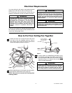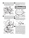
SWITCH HOUSING
MOUNTING SCREW (3)
SWITCH HOUSING
ASSEMBLY
MOTOR CONNECTOR
SWITCH HOUSING
CONNECTOR
5
Figure 4
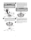
4. The blade flanges have an interlocking feature that
must be fully engaged before tightening the screw.
Make sure all the flanges are properly engaged
and then tighten the flange screws. If one of the
flanges does not seat properly on the motor hub,
loosen the adjacent flange screws, re-engage and
reseat the flanges, then tighten the screws again.
BLADE/FLANGE
ASSEMBLY
SWITCH HOUSING
ADAPTER
M6 x 14mm CAPTIVE PAN
HEAD SCREW (2 per
blade/flange assembly)
MOTOR HUB
NOTCHED AREA
Figure 3
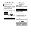
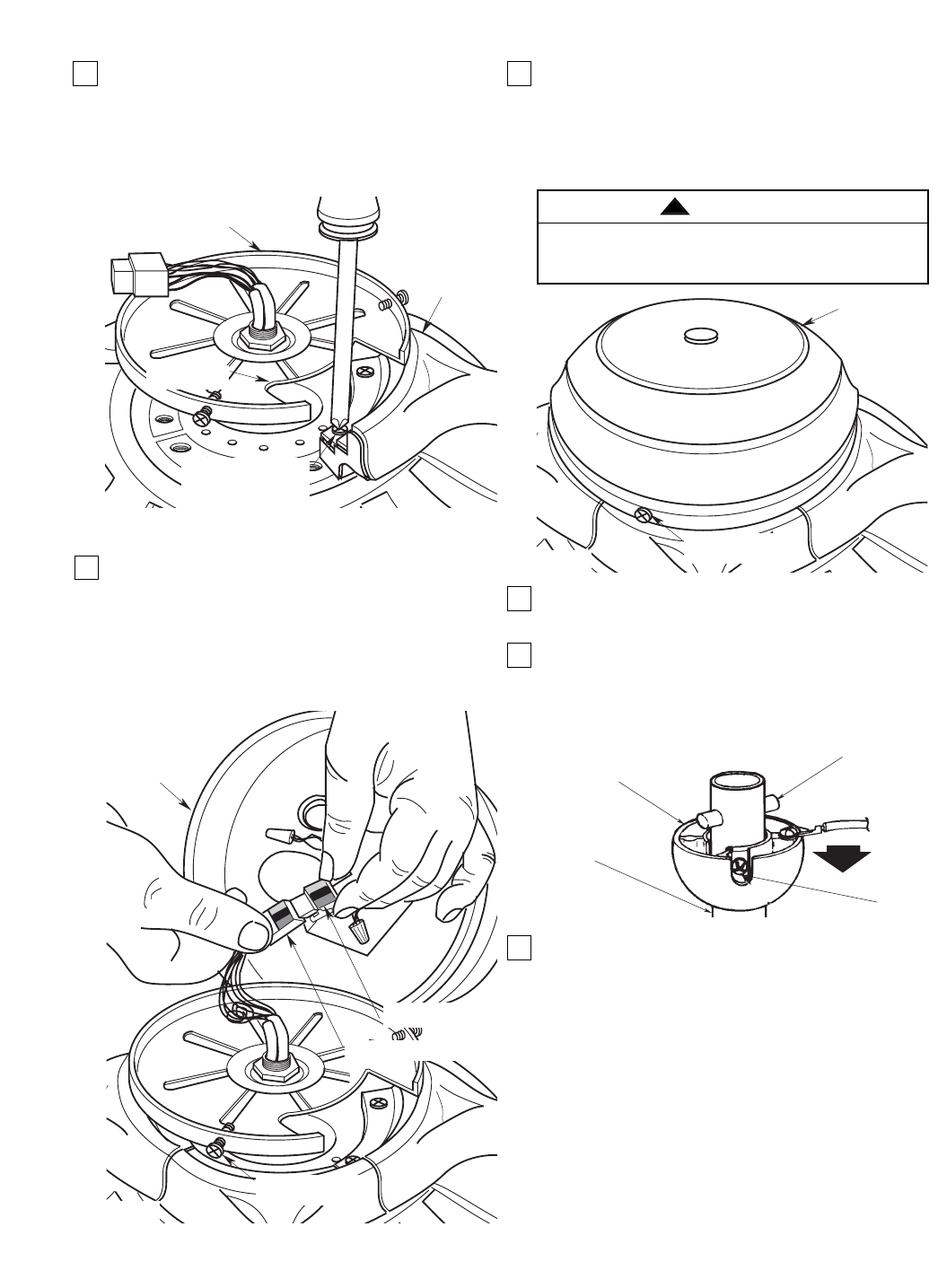
5. Remove and retain the three switch housing
mounting screws (Figure 4) from the switch
housing plate. Engage the connector of the switch
housing assembly with the motor connector
(Figure 4). The two connectors are keyed and
color-coded and must be mated correctly (color-to-
color) before they can be engaged. Make sure the
connector latch closes properly.
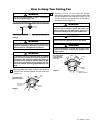
M4 x 12mm FLAT HEAD
SCREW (3)
SWITCH HOUSING
ASSEMBLY
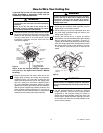
8. Remove the hanger ball by loosening the setscrew
in the hanger ball until the ball falls freely down the
downrod (Figure 6). Remove the pin from the
downrod, then remove the hanger ball. Retain the
pin and hanger ball for reinstallation in Step 9.
9. Separate, untwist and unkink the three 80” motor
leads. Route the motor lead wires through the
downrod. Remove the upper setscrew from the
motor coupling. Align the clevis pin holes in the
downrod with the holes in the motor coupling.
Install the clevis pin and secure with the hairpin clip
(Figure 7). The clevis pin must go through the
holes in the motor coupling and the holes in the
downrod. Be sure to push the straight leg of the
hairpin clip through the hole near the end of the
clevis pin until the curved portion of the hairpin clip
snaps around the clevis pin. The hairpin clip must
be properly installed to prevent the clevis pin from
working loose. Pull on the downrod to make sure
the clevis pin is properly installed. Reinstall the
upper setscrew in the motor coupling. Check that
the lower setscrew is tightened securely (Figure 7).
Figure 5
To avoid possible fire or shock, do not pinch wires
between the switch cup assembly and the switch
cup plate.
WARNING
!
PIN
SETSCREW
HANGER
BALL
DOWNROD
Figure 6
6. Position the switch housing assembly on the
switch housing plate and align the holes in the
switch housing assembly with the holes in the
plate. Secure the switch housing assembly by
installing the three M4 x 12mm flat head screws
(supplied) (Figure 5).
7. Carefully turn partially assembled fan upside down
and place in styrofoam form carton, in preparation
for final installation.
U.L. Model No.: CF452


