


6
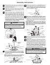
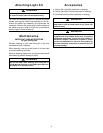
9. The fan comes with blue, black and white leads
that are 80-inches long. Before installing fan, mea-
sure up approximately 6 to 9-inches above the
ball/downrod assembly. Cut off excess leads and
strip back insulation 1/2-inch from end of leads.
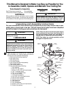
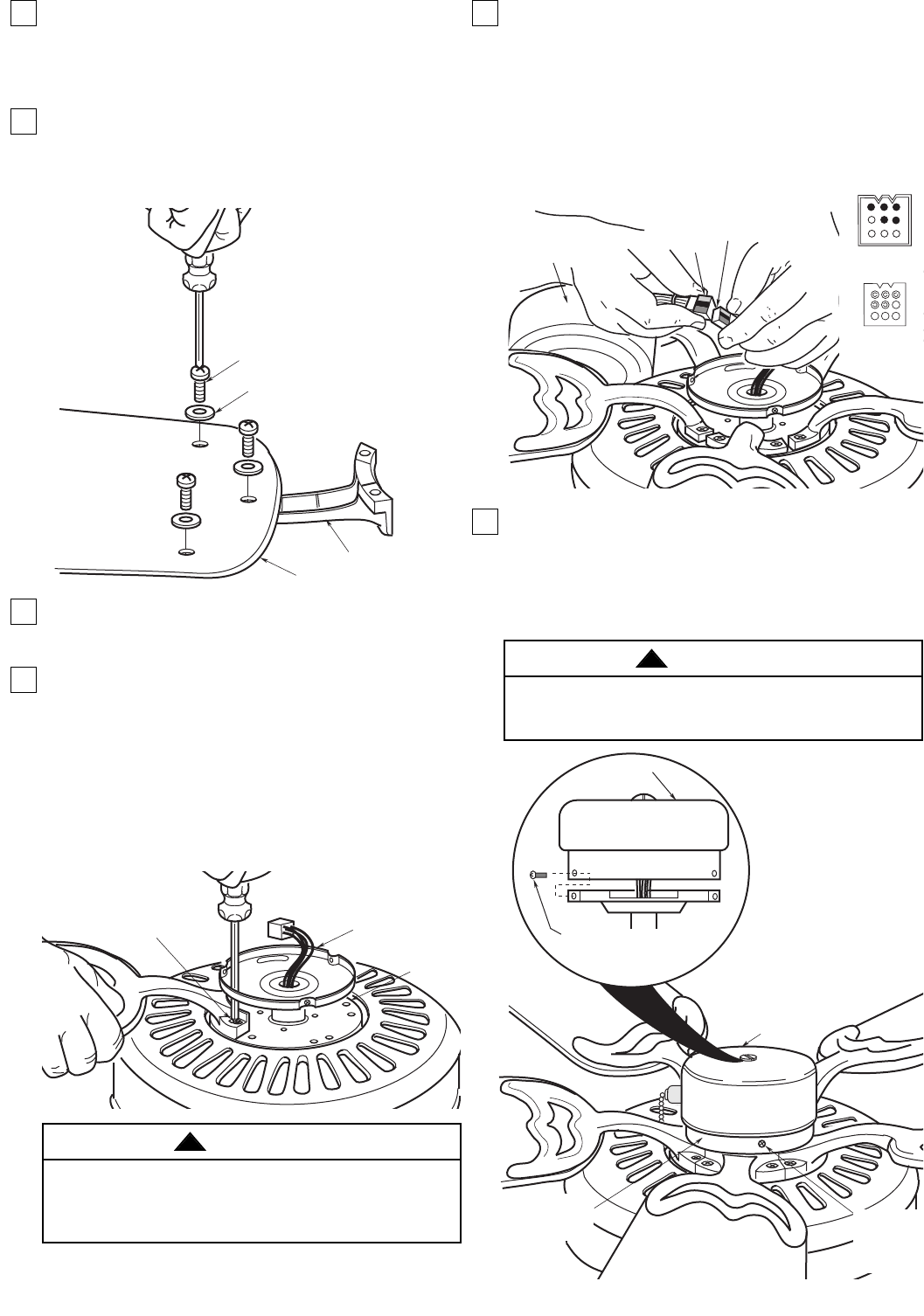
10. Use three 10-32 x 3/8" pan head screws and flat
washers (supplied) to secure flange to blade, as
shown below. Repeat for the remaining four
blades.
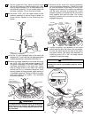
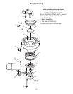
11. Use the 10 round recessed holes in the motor hub
marked with "5" and install the five blade assemblies
(ordered separately) in accordance with Step 12.
12. Attach one blade assembly to the motor hub using
two 10-32 x 5/8" oval head screws (supplied). Do
not tighten completely at this time. Install remain-
ing blade assemblies in the same way. Gently
snug all flange screws to the motor hub, working
around the hub in a clockwise sequence. Next,
securely tighten all flange screws, again working in
a clockwise sequence. Failure to follow this proce-
dure could result in fan wobble. This completes
the blade installation.
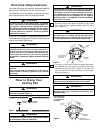
13. Remove the fan motor and housing assembly
from the styrofoam packaging. Position the motor
so that the bottom of the motor is facing you.
Engage the connector of the switch cup assembly
with the motor connector by aligning the V-notch
shaped keyways and pressing the connectors
firmly together until they fully mate. The V-notch
keyways prevent the connectors from being
engaged improperly.
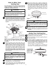
14. Position the switch cup assembly on the motor
switch plate and align the holes in the cup assem-
bly with the holes around the side of the switch
cup plate. Secure The switch cup assembly by
installing three 8-32 x 3/8" flat head screws
(supplied in loose parts bag).
SWITCH
HOUSING
ASSEMBLY
SWITCH CUP
ASSEMBLY
8-32 X 3/8"
FLAT HEAD
MOUNTING
SCREWS (3)
SWITCH CUP
PLATE
8-32 x 3/8"
FLAT HEAD
MOUNTING
SCREWS (3)
SWITCH
CUP
PLATE
To avoid possible fire or shock, do not pinch wires
between the switch cup assembly and the switch
cup plate.
WARNING
!
To reduce the risk of personal injury, do not bend the
blade flanges when installing the blades or cleaning
the fan. Do not insert foreign objects between rotat-
ing fan blades.
WARNING
!
BLADE FLANGE
FAN BLADE
10-32 x 3/8" PAN
HEAD SCREW (3)
FLAT WASHER (3)
SWITCH HOUSING
PLATE
MOTOR
HUB
1/4-20 x 1/2"
FLANGE SCREWS (2)
(INSTALL THROUGH SLOT
IN SWITCH HOUSING PLATE)
MOTOR
CONNECTOR
SWITCH
HOUSING
CONNECTOR
SWITCH HOUSING
ASSEMBLY
SWITCH CUP
CONNECTOR
MOTOR
CONNECTOR