7
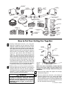
CEILING
CEILING
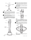
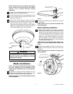
SUPPORT CABLE
HANGER
BRACKET
OUTLET BOX
CEILING JOIST
WOOD MEMBER
(2" x 4" Approx.)
Figure 8
HANGER BALL TAB
HANGER BALL/DOWNROD
ASSEMBLY
ATTACH SUPPORT WIRE
TO CEILING SUPPORT
WIRE
Figure 9
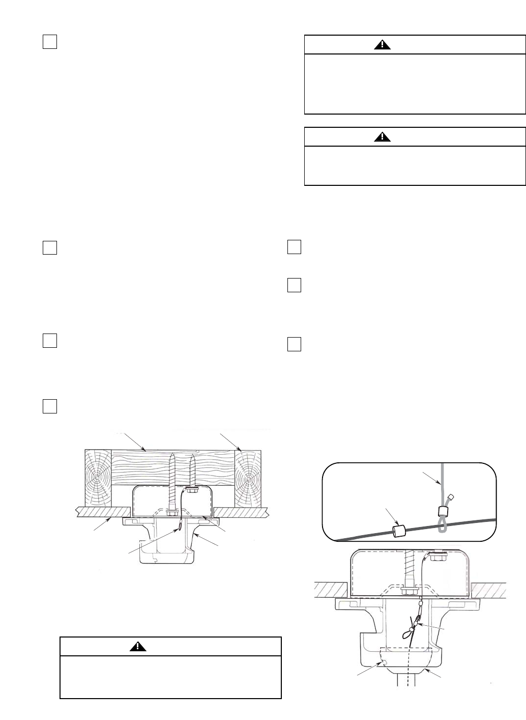
1. Securely attach the ceiling support wire to the
ceiling joist or structural member using the 3/8 x 2”
hex lag bolt and flat washer. Drill a maximum
diameter 1/4” pilot hole into the supporting member
to prevent splitting or cracking. Install a washer
onto the screw and insert the screw through one of
the loops (Figure 8). Securely tighten the screw
into the structure.
IMPORTANT
Do not use any lubricant when installing the lag
bolts.
IMPORTANT
The pilot holes should be drilled no larger than
the minor diameter of the mounting screw
threads, and at least 1-1/2 inches of the threaded
part of the mounting screw should be inches
secured into a structural wood joist to provide
secure mounting.
2. Drill a second maximum diameter 1/4” pilot hole up
through the center of the electrical box (Figure 8).
Install the hanger bracket assembly using 3/8 x 5”
lag bolt and 3/8” flat washer. Route the electrical
supply wires through the opening provided on the
hanger bracket. Do not completely tighten the lag
bolt, leave it lose enough such that the hanger
bracket assembly can be freely rotated against the
electrical box.
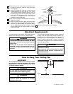
3. Temporarily hang the ceiling fan assembly on the
hanger bracket, be sure the hanger ball groove
engages the hanger bracket tab. Rotate the fan
assembly and hanger bracket to the desired
orientation. Remove the fan assembly from the
hanger bracket.
4. Completely tighten the center lag bolt while holding
the hanger bracket in the desired position.
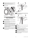
6. Carefully lift the fan assembly and seat the
hangerball/downrod fan assembly into the hanger
bracket. Be sure the groove in the hanger ball lines
up with the tab on the hanger bracket
(Figure 9).
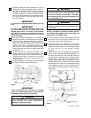
7. Install the end of the fan support cable through the
center of the small brass bushing (supplied). Do
not allow the bushing to slide down the cable and
into the downrod. Now pass the fan support cable
through the loop provided on the free end of the
ceiling support cable previously installed into the
building structure. Next, pass the fan support cable
back through the center of the small brass bushing
in the opposite direction as the first pass. Pull as
much cable as possible through the brass bushing
(Figure 9A).
IMPORTANT
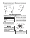
If you are installing your ceiling fan on a sloped
ceiling, the hanger bracket must be mounted with
the hanger ball opening facing up-slope.
Hanger bracket must seat firmly against outlet
box. If the outlet box is recessed, remove wall
board until bracket contacts box. If bracket
and/or outlet box are not securely attached, the
fan could wobble or fall.
WARNING
5. Position the motor lead wires and support cable on
the back side of the hanger bracket for final
connection to the electrical supply wires.
Failure to seat tab in groove could cause
damage to electrical wires and possible shock
or fire hazard.
WARNING
To avoid possible fire or shock, do not pinch
wires between the hanger ball/downrod
assembly and hanger bracket.
WARNING
U.L. Model No.: CF3300
NOTE: If not done so already, carefully remove
the masking tape applied to the motor leads and
support wire to complete wiring.
SHORT CABLE
ASSEMBLY
ATTACHED TO
CEILING
SMALL BRASS
BARREL BUSHING


