7
U.L. Model No.: CF230
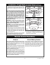
Installation of Blades & Light Assembly (continued)
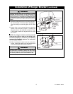
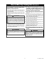
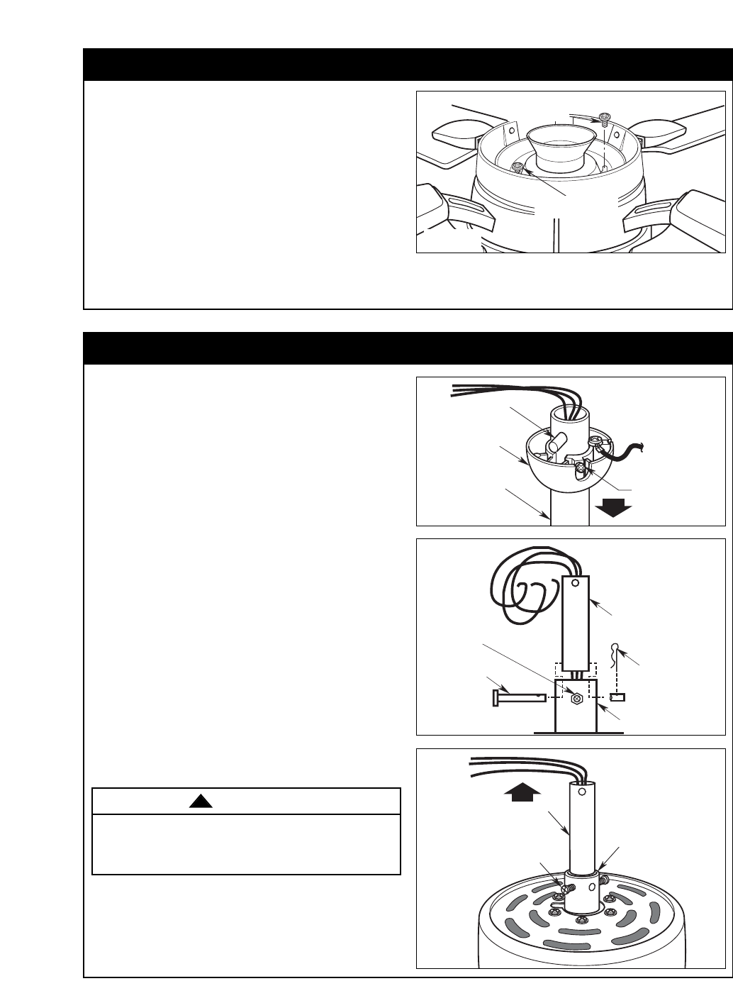
REINSTALL FAN
MOTOR SCREW
RETIGHTEN TWO FAN
MOTOR SCREWS
Figure 8
5. Position the light kit plate assembly onto the fan
motor assembly, careful to not pinch any wires
during installation.
6. Rotate the light kit plate assembly counter-
clockwise to engage the two key slots with the two
screws in the fan motor assembly.
7. Reattached the screw (removed in Step 3) into the
light kit plate assembly and securely tighten the
three screws (Figure 8).
NOTE: Do not engage the light bulb at this time.
NOTE: Continue to Close-to-the-Ceiling instal-
lation if needed.
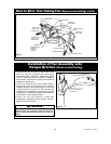
How to Assemble Your Ceiling Fan (Standard)
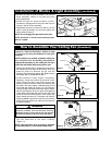
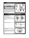
DOWNROD
SETSCREW (2)
MOTOR COUPLING
Figure 11
Proceed to "Close-To-The-Ceiling" section on page
11 if you are not using the downrod to hang your
ceiling fan.
NOTE: Carefully turn partially assembled ceiling fan
over and place into the packing styrofoam to
complete the assembly of your ceiling fan. Be extra
careful with the blades while turning the fan over.
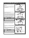
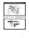
1. Remove the hanger ball by loosening the setscrew in
the hanger ball until the ball falls freely down the
downrod (Figure 9). Remove the pin from the
downrod, then remove the hanger ball. Retain the pin
and hanger ball for reinstallation in Step 7.
2. Loosen setscrew in motor coupler if necessary.
Separate, untwist and unkink the three 80” motor
leads. Route the motor lead wires through the
downrod. Align the clevis pin holes in the downrod with
the holes in the motor coupler. Install the clevis pin and
secure with the hairpin clip (Figure 10). The clevis pin
must go through the holes in the motor coupler and the
holes in the downrod. Be sure to push the straight leg
of the hairpin clip through the hole near the end of the
clevis pin until the curved portion of the hairpin clip
snaps around the clevis pin. The hairpin clip must be
properly installed to prevent the clevis pin from working
loose. Pull on the downrod to make sure the clevis pin
is properly installed.
It is critical that the clevis pin in the motor coupler is
properly installed and the setscrew securely
tightened. Failure to verify that the pin and setscrew
are properly installed could result in the fan falling.
WARNING
!
PIN
HANGER BALL
SETSCREW
DOWNROD
Figure 9
MOTOR COUPLING
SETSCREW (2)
CLEVIS PIN
HAIRPIN
CLIP
DOWNROD
Figure 10
3. While pulling up on the downrod, securely tighten
the two setscrews in the motor coupling
(Figure 11).
NOTE: The setscrews must be properly installed
as described above, or fan wobble could result.


