


4
© 2011 Emerson Climate Technologies
Printed in the U.S.A.
AE8-1385
Application Engineering
BULLETIN
INTRODUCTION
Overview
CoreSense
™
Diagnostics is a breakthrough innovation
for troubleshooting residential air conditioning and heat
pump systems. The CoreSense Diagnostics module
is easily installed in the unit electrical panel near the
compressor contactor. By using the compressor as
a sensor, CoreSense Diagnostics helps the service
technician more accurately troubleshoot system and
compressor fault conditions.
CoreSense Diagnostics also provides compressor
and system protection through its proprietary lockout
feature. Depending on the severity and frequency of
the fault that caused the trip condition, the CoreSense
Diagnostics module can lockout the compressor
contactor to prevent damage to the compressor and
system components. Less severe fault conditions
resulting in an occasional trip will not result in a lockout
condition.
Flashing LEDs communicate ALERT and LOCK codes
to the service technician.
Application Restrictions and Types
The CoreSense Diagnostics (571-0072-00) module
is designed and qualifi ed for use with ZPS*K5 single-
phase Copeland Scroll
®
UltraTech
™
compressors.
Product Specifi cations
Operating Temp: - 40° to 150°F (- 40° to 65°C)
Storage Temp: - 40° to 175°F (- 40° to 80°C)
Supply Voltage: 18 to 28VAC , 48 to 62Hz
Module Current Sensing Range: 2 to 30A
Maximum Power Consumption: 2.5 VA (Excluding
solenoid load)
INSTALLATION
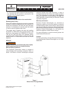
Mounting
Four #8 or #10 self tapping or sheet metal screws are
required for installation of the module. The maximum
mounting screw torque is 20 in.lbs. Locate the
module near the compressor contactor (wire routing
for compressor run, common, and start wires will be
easier in this position). The module can be mounted
in any orientation and LEDs should be visible for ease
of service.
The compressor’s run (R), common (C), and start (S)
wires are routed through the holes in the CoreSense
module marked “R”,”C”, and “S”. See Figure 1.
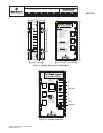
Terminal Description
The terminals for the CoreSense Diagnostics module
are ¼” spade terminals.
• COMMON (C)
The 24 volt common terminal for module power.
• DEMAND (Y)
The demand terminal requires a 24VAC signal
measured with respect to the COMMON (C)
terminal when there is a call for heating or
cooling. A signal above 6VAC indicates the
thermostat wants the compressor to be on, while
0-6VAC signal indicates the thermostat wants
the compressor to be off.
• SECOND STAGE DEMAND (Y2)
The demand (Y) and second stage demand
(Y2) terminals require a 24VAC signal measured
with respect to the COMMON (C) terminal when
there is a call for heating or cooling. A signal
above 10VAC indicates the thermostat wants the
Ultratech solenoid to be energized, while 0-10VAC
signal indicates the thermostat wants the Ultratech
solenoid to be deenergized.
• PROTECTION (PROT)
The protection terminal is internally connected
to the COMMON terminal through a solid state
switch.
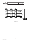
• POWER (R)
The module requires a constant 24VAC supply
power to this terminal. The module must receive
an independent power supply in order to operate
properly. See Figure 4.
• Thermostat Communication (L)
Provides a 24V signal to an indoor thermostat
indicating the number of ALERT fl ashes displayed
on the module. (Reference thermostat manual for
available capability)
• Solenoid (DC SOL)
Provides a connection to the Copeland Scroll
UltraTech second stage compressor solenoid. This
solenoid is internal to the compressor, and has
a voltage range of 18 to 28VDC. Please refer to
bulletin AE-1311 for information on the Copeland
Scroll
®
UltraTech
®
compressor.