


2
SPECIFICATIONS
ELECTRICAL RATINGS [@ 77°F (25°C)]:
Input Voltage: 25 VAC 50/60 Hz
Max.InputCurrent@25VAC: 0.45 amp
Relay Load Ratings:
Valve Relay: 1.5 amp @ 25 VAC 50/60 Hz 0.6 pf
Ignitor Relay: 6.0 amp @ 120 VAC 50/60 Hz (resistive)
Inducer Relay: 2.2 FLA–3.5 LRA @ 120 VAC
Circulator Relay: 14.5 FLA–25.0 LRA @ 120 VAC
Flame Current Requirements:
Minimum current to insure flame detection: 1 µa DC*
Maximum current for non-detection: 0.1 µa DC*
Maximum allowable leakage resistance: 100 M ohms
*Measured with a DC microammeter in the flame probe lead
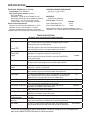
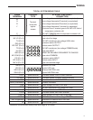
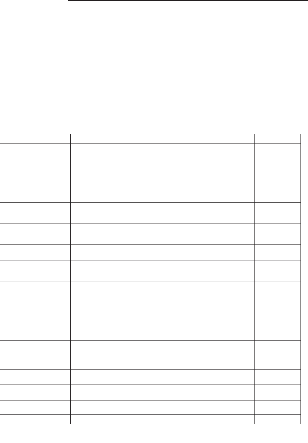
TIMING SPECIFICATIONS
(All times are in seconds, unless noted otherwise
Event Denition 50M56-743
Pre-Purge
The period of time intended to allow for the dissipation of any unburned
gas or residual products of combustion at the beginning of a furnace
operating cycle prior to initiating ignition
30
Trial for Ignition
Period (TFI)
The period of time between initiation of gas flow and the action to
shut off the gas flow in the event of failure to establish proof of the
supervised ignition source or the supervised main burner flame.
4
Ignition Activation
Period (IAP)
The period of time between energizing the main gas valve and
deactivation of the ignition means prior to the end of TFI
2
Retries
The additional attempts within the same thermostat cycle for ignition
when the supervised main burner flame is not proven within the first
trial for ignition period.
2 times
Recycles
The additional attempts within the same thermostat cycle for ignition
after loss of the supervised ignition source or the supervised main
burner flame.
3
Valve Sequence
Period
Valve sequence period equals 4 seconds trial for ignition period x
(1 initial try + 2 retries) + 12 seconds.
12
Interpurge
The period of time intended to allow for the dissipation of any unburned
gas or residual products of combustion between the failed trial for
ignition and the retry period.
60
Post-Purge
The period of time intended to allow for the dissipation of any unburned
gas or residual products of combustion at the end of a furnace burner
operating cycle. Post-purge begins at the loss of flame sense.
25
Lockout Time
ANSI standard rated module timing.
275
Heat Delay-To-Fan-On
The period of time between proof of the supervised main burner flame
and the activation of the blower motor at Heat speed.
30
Heat Delay-To-Fan-Off*
The period of time between the loss of a call for heat and the
deactivation of the blower motor at Heat speed.
100/150*
Cool Delay-To-Fan-On
The period of time after a thermostat demand for cool before energizing
the circulator blower motor at Cool speed.
6
Cool Delay-To-Fan-Off*
The period of time between the loss of a call for cool and the
deactivation of the blower motor at Cool speed.
45
Ignitor Warm-up
(1st 64 attempts)
The length of time allowed for the igniter to heat up prior to the initiation
of gas flow.
17
Maximum Ignitor
Warm-up
In the event of a retry, the warm-up time will be increased by one
second, up to a maximum of 19 seconds, and locked at that duration
19
Auto Reset
After one (1) hour of internal or external lockout, the control will auto-
matically reset itself and go into an auto restart purge for 60 seconds.
60 minutes
Electronic Air Cleaner Yes
*This time will vary depending on option switch position. The control is factory set at 150 seconds HEAT
delay-to-fan-off. See OPERATION section for further information
OPERATING TEMPERATURE RANGE:
-40° to 176°F (-40° to 80°C)
HUMIDITY RANGE:
MOUNTING:
Surface mount multipoise
Timing Specs: (@ 60 Hz)
maximum
Flame Establishing Time: 0.8 sec
Flame Failure Response Time: 2.0 sec
Gases Approved: Natural, Manufactured, Mixed, Liquified
Petroleum, and LP Gas Air Mixtures are all approved for use.