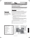
INTEGRATED FURNACE
CONTROL MODULE
TROUBLESHOOTING
GUIDE
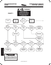
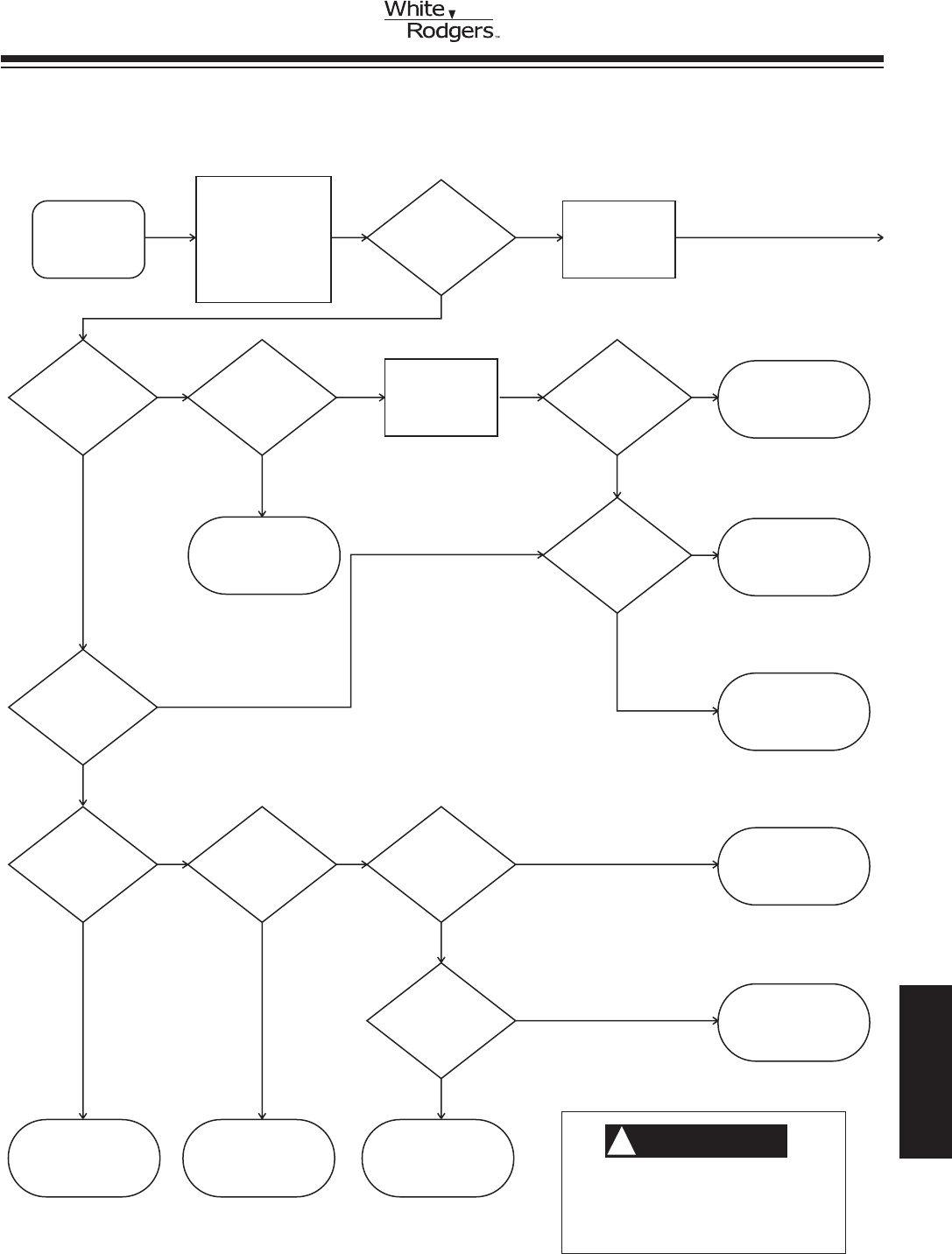
Place thermostat
system switch in
cooling mode and fan
switch in AUTO
position. Lower
temperature selection
lever to call for a
cooling cycle. R & Y
contacts close.
Return thermostat
to desired
setting.
With door
switch closed,
jumper control
terminals
R & Y.
Cooling
Cycle
Check
Does indoor
blower energize
at cooling
fan speed?
YES
YES
NO
NO
YES
NO
YES
NO
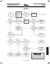
Repair low
voltage wiring to
thermostat. Check
operation.
Does
indoor blower
energize at
cooling fan
speed?
Is
thermostat terminal
Y connected to furnace
terminal Y?
Does
indoor blower
energize at
heating fan
speed?
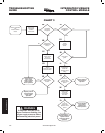
Is 120V present
at primary of
transformer?
Is 24V
present at
control terminals
G & C?
Is 24V
present across
control terminals
Y & C?
Replace control.
Check operation.
Replace
transformer.
Check operation.
Repair wiring
between control and
transformer
primary. Check
operation.
Correct 120V
power supply to
control. Check
operation.
Repair low
voltage wiring to
thermostat.
Check operation.
Correct wiring
from thermostat
terminal Y to Y on
furnace. Check
operation.
YES
Indoor blower
fault. Repair or
replace motor.
Check operation.
NO
Is 120V
present at
control terminals
COOL & CIR
NEUTRAL?
2A 2B
2E
2D2C 2F
2H
2K2J
2G
YES
NO
YES
YES
YES
NO
NO
Is 120V
present at
control terminals
LINE & LINE
NEUTRAL?
2L
YES
Repair low
voltage wiring
from transformer to
control. Check
operation.
NO
Is 24V
present at
control terminals
R & C?
2I
NO
CHART 2
WARNING
!
If diagnostic indicator (LED)
shows continuous ashing, turn
off gas supply at source before
disconnecting electrical power!
TECHNICAL HELP
www.white-rodgers.com
191


