


4
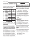
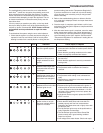
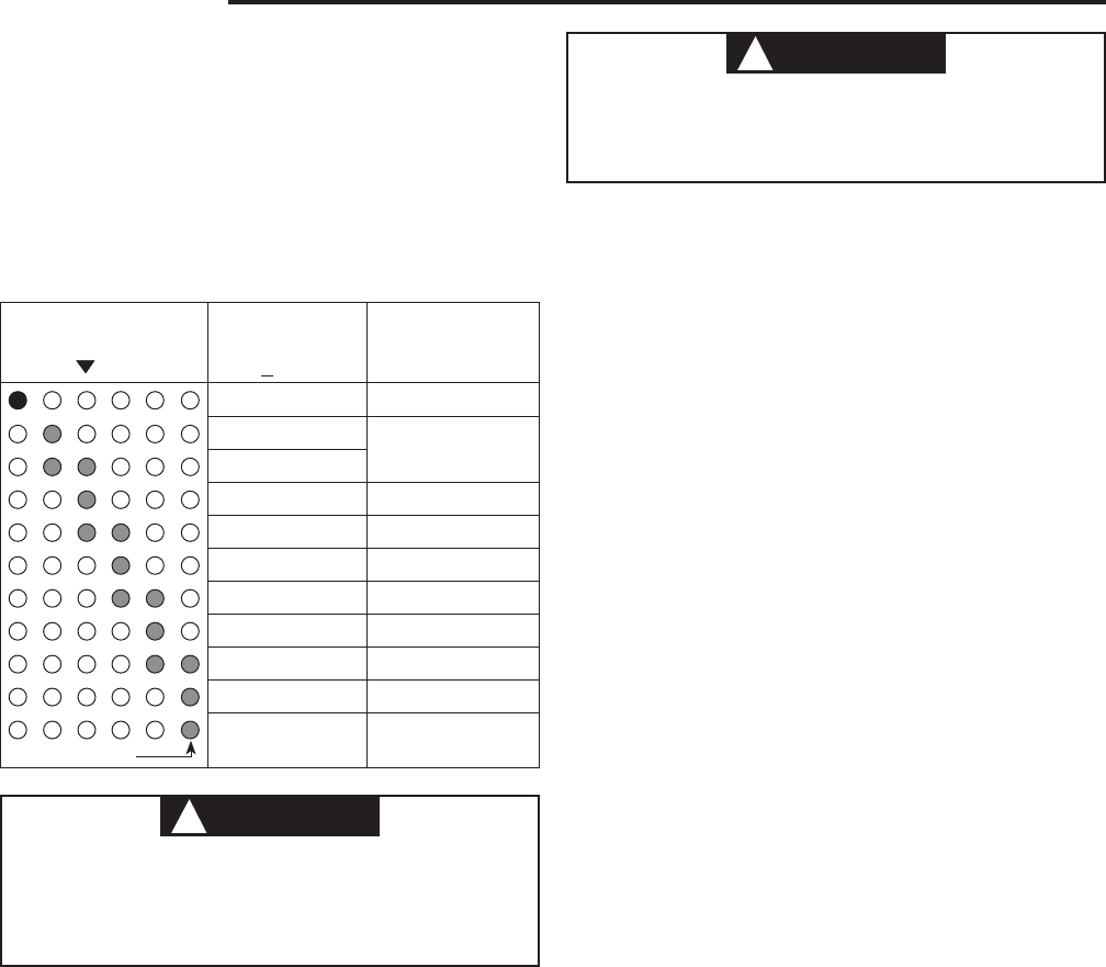
Table 1. Temperature Settings
Display
A B C
Approximate
Temperature
( +10
o
F)
Approximate
Time to Cause
Injury
70 (Vacation)
N/A
110
115
120
5 minutes
125
130
30 seconds
135
140
5 seconds
145
150
1.5 seconds
160 under 1 second
Flashing
WARNING
!
Never allow small children to use a hot water tap, or
to draw their own bath water. Never leave a child or
impaired person unattended in a bathtub or shower.
Scald burns can result
WARNING
!
Scald burns occur in under one second with 160°F
water, which this thermostat will deliver if the
temperature is set at “VERY HOT”. Lower settings of
the temperature will reduce the risk of scald and will
reduce your fuel bill.
Press and release the HOTTER button until you have
reached the desired setting. HOLDING DOWN THE BUTTON
WILL NOT CONTINUE TO RAISE THE SETTING. The button
must be pressed and released for each temperature change
desired.
To avoid scald injury, set the control to the lowest setting
which will deliver your needed hot water. Refer to Table 1 to
determine the approximate temperature setting, and the ap-
proximate time for scald injury at that temperature.
3. When you have completed setting the control wait 30
seconds to see that the temperature indicators go off and
the control enters “Sleep” mode. ALL OF THE TEMPERA-
TURE INDICATORS WILL BE OFF DURING NORMAL
OPERATION. If any time you see the indicators on, there
may be a system error and you should consult the “Trou-
bleshooting” section of this document, or contact a trained
service professional.
If you use hot water frequently and in short spurts, water tem-
perature can occasionally exceed the temperature setting by
up to 30°F because of the dynamics of the appliance. Keep
this in mind when you are selecting a temperature higher than
the factory default setting.
Be sure to protect babies and the infirm or others with im-
paired mobility who cannot get out of the hot water quickly.
They are the people most commonly hurt in scald injuries and
in need of lower temperature and other protection like super-
vision, point-of-use temperature control equipment or a sys-
tem mixing valve. A point-of-use valve or system mixing valve
can be obtained from your local plumber.
Checking the temperature setpoint may be performed at any
time by the procedure described on step 1 of “Temperature
Regulation” on page 3. No other action is needed for checking
temperature setpoint.
SHUTTING OFF THE APPLIANCE
Vacation Shutdown
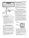
1. “Wake up” the temperature indicators by holding down
both the COOLER and HOTTER temperature adjustment
buttons at the same time for one second (see Figure
2). One or two of the temperature indicators will light up.
Make a note as to which indicators are illuminated so that
you can reset the control to the same setting when you
return from vacation.
2. Press and release the COOLER button as many times as
needed until the green leftmost indicator is only lit. This
temperature setting is approximately 70°F. Leave the gas
turned on.
3. When returning from vacation reset the temperature to
that you noted in step 1.
Complete Shutdown
1. Turn off the electrical disconnect on the appliance, or
remove the plug from the receptacle, whichever applies.
(Don’t worry; the Intelli-Vent™
control will remember your
correct temperature setting.)
2. Turn off the gas supply to the water heater. The water
heater is now completely shut down.
3. To restart the water heater, follow the instructions in the
section “Operating Instructions”.
There are no user serviceable parts in this control. The con-
trol is supplied with tamper resistant screws. DO NOT attempt
to repair or adjust the control. If you experience problems,
discontinue use and replace the control immediately. Con-
tinuing to use a damaged control could result in fire and/
or explosion.
Service
If you wish to verify that the water heater is operating properly:
1. Make sure there is power to the water heater.
2. Make sure that the gas is turned on to the water heater.
3. Initiate a call for heat by either drawing hot water from a
nearby faucet or raising the temperature setting (see sec-
tion “Temperature Regulation”).
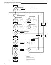
4. Watch the ignition sequence and compare it to the “Se-
quence of Operation” chart on page 6.
5. Note any error codes that appear and proceed to the next
section “Troubleshooting”.
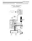
INSTALLATION