


2
INSTALLATION
REPLACEMENT INFORMATION
REMOVINGOLDCONTROL
1. Turn off gas supply to the water heater at the manual gas
shut-off valve. This valve is typically located beside the
water heater.
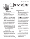
2. Locate the gas control valve/thermostat. Before performing
any maintenance, turn the temperature dial on the gas
control valve/thermostat to the lowest setting. (See To light
Appliance Figure 2)
3. On the top of the gas control valve turn the gas control
knob to the “Off” position. (See To light Appliance Figure A)
NOTE:OntheWhite-Rodgersgascontrolvalve/
thermostattheknobstopmustrstbeslightly
depressedbeforeturningthegascontrolknob.
4. Close the cold water inlet valve to the water heater and
open a nearby hot water faucet.
5. Connect a hose to the drain valve and terminate it to an
adequate drain. Open water heater drain valve by turning
handle counterclockwise to drain water heater tank.
IMPORTANT:DONOTproceedtothefollowingsteps
untilthewaterheateriscompletelydrained.
6. On some water heaters, the outer door may need to be
removed.
7. If control doesn’t have a piezo ignitor, skip to step (8) or
disconnect the piezo ignitor wire from the piezo ignitor
button.
NOTE:Therearetwotypesofignitors.Ifyouhavethe
squareignitor,slidetheignitorbracketbackwardaway
fromthegasvalvetoremoveit.Ifyouhavearound
ignitor,rstremovetheignitorfromthebracketby
depressingfrontandrearholdingtabsandlift.Next
removeignitorbracketfromthegasvalve.Keepignitor
andbracket.
8. Disconnect the thermocouple, pilot tube, and manifold
(burner) tube. Some control may have two wires (flying
leads) attached to the thermal switch that must be
disconnected as well.
9. Disconnect the union joint in the gas piping. Disconnect the
remaining pipe from the gas control valve/thermostat.
10. Remove the control by turning it counterclockwise. If
needed, a short piece of ½” black iron pipe can be screwed
into the control inlet to increase leverage.
INSTALLING NEW CONTROL
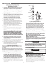
All piping must comply with local and state ordinances or with
the National Fuel Gas Code (ANSI Z223.1–NFPA 54), which-
ever applies.
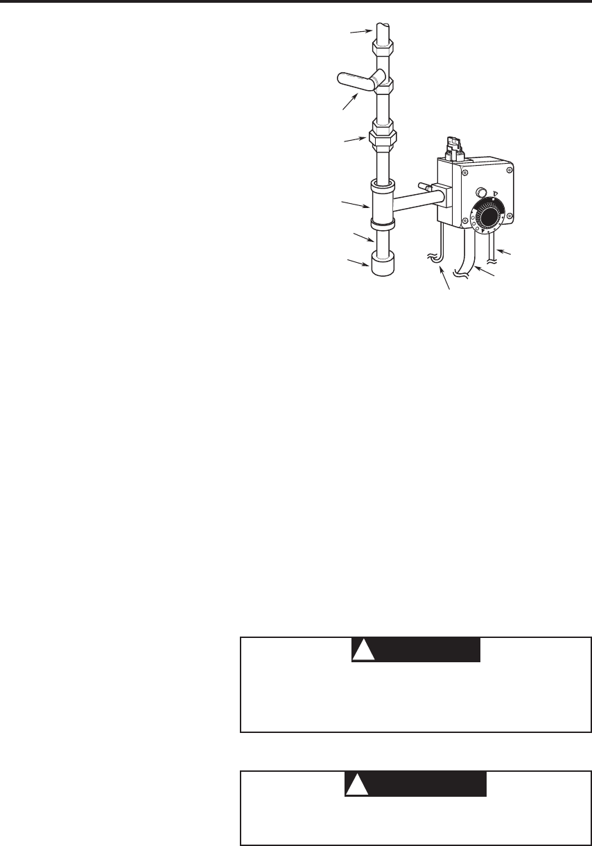
Dirt or contamination in the gas line can block the control from
operating creating a risk of explosion, injury or death. To protect
the control from dirt/contamination, a drip leg or sediment trap
(see Figure 1) must be installed in the piping to the control.
1. To replace the gas control valve/thermostat, reassemble
in reverse order. When replacing the gas valve, use a
short piece of pipe to help turn control. (Clockwise) DO
NOT OVER TIGHTEN or damage may result. Use an
approved pipe compound on the threads that screw into
the tank and to the gas pipe that screw into the gas control
valve/thermostat. Do not use TEFLON tape. Do not apply
compound to first two threads on gas pipe.
2. Reconnect the gas piping to the gas control valve/
thermostat. Use new black iron pipe that has been properly
reamed. If old pipe is used, be sure it is clean and free from
rust and scale.
To pilot
burner
To main burner
To thermocouple
A
B
C
P
I
L
O
T
L
I
G
H
T
I
N
G
L
O
W
H
O
T
V
E
R
Y
H
O
T
RISK OF SCALDING
INCREASES WITH
HOTTER WATER
CAUTION:
Figure1.Typicalgasconnection
Drip leg
(sediment trap)
Pipe cap
Tee
Union
(metal-to-metal)
Gas shut-off
valve
Gas supply
pipe
To pilot
burner
To main burner
To thermocouple
A
B
C
P
I
L
O
T
L
I
G
H
T
I
N
G
L
O
W
H
O
T
V
E
R
Y
H
O
T
RISK OF SCALDING
INCREASES WITH
HOTTER WATER
CAUTION:
Figure1.Typicalgasconnection
Drip leg
(sediment trap)
Pipe cap
Tee
Union
(metal-to-metal)
Gas shut-off
valve
Gas supply
pipe
3. If control had an ignitor, transfer the ignitor and bracket
removed from the old gas control valve to the new one.
4. Reconnect manifold tube (burner), pilot tube, ignitor
wire (if present), flying leads (if present), Thermocouple
nut (thermocouple nut should be hand tightened and
then turned an additional ¼ turn with small wrench. DO
NOT OVERTIGHTEN. Do not use pipe joint compound
or TEFLON tape on manifold, pilot, and thermocouple
connections.
5. Reconnect union. DO NOT use joint compound or TEFLON
tape on union connection.
6. Close the water heater drain valve by turning the handle to
the right (clockwise). Open the cold water supply valve to
the water heater to fill the water heater tank.
NOTE:Thecoldwatersupplyvalvemustbeleftopen
whenthewaterheaterisinuse.
Keep the nearby hot water faucet open for 3 minutes after a
constant flow of water is obtained to purge the lines of any
excess air. Check all new water piping for leaks. Repair as
needed.
CAUTION
!
Neverusethiswaterheaterunlessitiscompletelylled
withwater.Topreventdamagetothetank,thetankmust
belledwithwater.Watermustowfromthehotwater
faucetbeforeturningONgastothewaterheater.
7. Turn on gas shutoff valve.
WARNING
!
DONOTUSEOPENFLAMEORANYKINDOFSPARKTO
CHECKFORLEAKS.Seriousinjuryofdeathfromreor
explosioncouldresult.
8. BEFORELIGHTINGTHEPILOT,CHECKTHEGAS
LINESFORLEAKS.Use a soapy water solution. DO NOT
test for gas leaks using a match or open flame.
Brush the soapy water solution on all gas pipes, joints,
and fittings. Check for bubbling soap indicating you have a
leak. Turn OFF the gas and make the necessary repairs.
Recheck for leaks. Rinse off soapy solution and wipe dry.
9. Affix the new Lighting instruction label on the water heater
to cover the existing label.