www.white-rodgers.com
185
TECHNICAL HELP
1E78-151
CONFIGURATION AND
TYPICAL WIRING DIAGRAMS
Base
Back of
Thermostat Body
RC
ELEC GAS
G RH
Y O B
W
W906
W904
Elec/Gas
Switch
W903
Mounting
Hole
Mounting
Hole
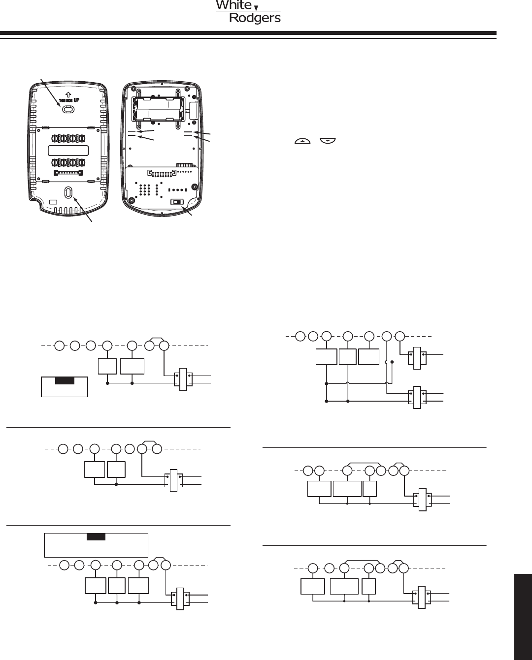
W903 - clip to disable EMR feature
W904 - clip for Celcius display
W905 - clip for hydronic system
Reset Operation
If a voltage spike or static discharge blanks out the display or
causes erratic thermostat operation you can reset the thermostat
by pressing , and TIME at the same time. This also
resets the factory defaults. If the thermostat has power, has been
reset and still does not function correctly contact your heating/
cooling service person or place of purchase.
W905
W906 - clip for 5/1/1 day programming
RH
24 VAC
120 VAC
Hot
Neutral
THERMOSTAT
SYSTEM
G W
Figure 2. Typical wiring diagram for
heat only, 3-wire, single transformer systems
TRANSFORMER
Heating
System
Fan
Relay
Y
RC
JUMPER
WIRE
OB
For 2-wire Heat only,
attach to RH and W
NOTE
RH
Y
24 VAC
120 VAC
Hot
Neutral
TRANSFORMER
THERMOSTAT
SYSTEM
G W
Figure 3. Typical wiring diagram for
cool only, 3-wire, single transformer systems
Cooling
System
Fan
Relay
RCOB
JUMPER
WIRE
RH
Y
24 VAC
120 VAC
Hot
Neutral
THERMOSTAT
SYSTEM
G W
Figure 4. Typical wiring diagram for
heat/cool, 4-wire, single transformer systems
TRANSFORMER
Heating
System
Fan
Relay
Cooling
System
RC
JUMPER
WIRE
OB
RED jumper wire (provided with thermostat) must be
connected between thermostat RH and RC terminals
for proper thermostat operation with this system.
NOTE
RH
Y
24 VAC
120 VAC
Hot
Neutral
THERMOSTAT
SYSTEM
G W
Figure 5. Typical wiring diagram for
heat/cool, 5-wire, two-transformer systems
HEATING
TRANSFORMER
Heating
System
Fan
Relay
Cooling
System
RC
24 VAC
120 VAC
Hot
Neutral
COOLING TRANSFORMER
OB
RH
Y
24 VAC
120 VAC
Hot
Neutral
THERMOSTAT
SYSTEM
G W
Figure 6. Typical wiring diagram for heat pump
with reversing valve energized in COOL
TRANSFORMER
Reversing
Valve*
RCOB
JUMPER
WIRE
Compressor
Contactor
JUMPER
WIRE
* Reversing valve is energized when the
system switch is in the COOL position
Fan
Relay
RH
Y
24 VAC
120 VAC
Hot
Neutral
THERMOSTAT
SYSTEM
G W
Figure 7. Typical wiring diagram for heat pump
with reversing valve energized in HEAT
TRANSFORMER
Reversing
Valve*
RCOB
JUMPER
WIRE
Compressor
Contactor
JUMPER
WIRE
* Reversing valve is energized when the
system switch is in the HEAT position
Fan
Relay
Figure 1


