


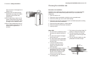
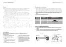

Fixing the installation plate
Drilling the Hole
1. Install the installation plate
horizontally over the structural
parts on the wall using the spaces
indicated on the plate, as shown in
the figure above.
2. In the case of tiled, concrete or
similar walls, create 5 mm-
diameter holes. Place anchorage
supports for the appropriate
assembly screws.
3. If expansion screws are used, the
holes must measure 11x20 or
11x26, with a distance of 450 mm
between each.
4. Fix the installation plate to the wall.
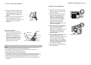
1. Determine the position of the hole
for the pipe using the installation
plate and drill the pipe hole (ø
65mm) so that it is titled slightly
downward.
2. Always use a pipe cover with an
opening when drilling a metal bar.
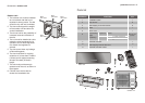
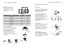
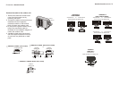
Placa de instalación
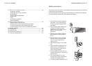
Fit the Installation Plate and drill holes
in the wall according to the wall
structure and corresponding mounting
points on the installation plate
(Dimensions are in “mm” unless
otherwise stated).
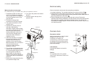
Wall
Indoor unit
Outdoor unit
5-7mm
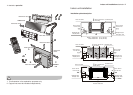
Do not put the end
of drain hose into water.
Do not block
water flow
by a rise.
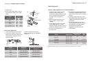
Connective pipe and drainage installation
Drainage
1. Run the drain hose sloping
downward. Do not install the drain
hose as illustrated below.
2. When connecting extension drain
hose, insulate the connecting part
of extension drain hose with a
shield pipe, do not let the drain
hose slack.
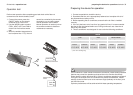
13 electrolux indoor unit installation
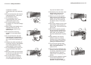
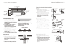
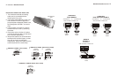
Connective pipe installation
1. For the left-hand and right-hand
piping, remove the pipe cover from
the side panel.
2. For the rear-right-hand and rear-left-
hand piping, install the piping as
shown. Bend the connective pipe to
be laid at 43mm height or less from
the wall.
3. Fix the end of the connective pipe.
Right back
piping
Pipe cover
(left)
Pipe
holder
Pipe cover
(right)
Right piping
Connective
pipe
Indoor unit
outline
43mm
indoor unit installation electrolux 14
Do not block
water flow
by a rise.
1. Pass the piping through the hole in
the wall.
2. Put the upper claw at the back of the
indoor unit on the upper hook of the
installation plate, move the indoor
unit from side to side to see that it is
securely hooked (see Fig.10 &
Fig.11).
Fastening the Indoor Unit
Upper hook
Lower hook
150mm del techo
above 120mm
from the wall
998
293
above 120mm
from the wall
Indoor unit outline
50
130
Refrigerant pipe
hole (left) Ø 65
119380380
50
130
41
Modelos 24000 Btu’s