


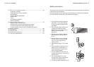
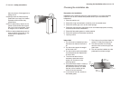
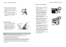
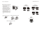
1. This illustration is for explanation purposes only.
2. Copper lines must be insulated independently
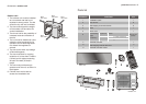
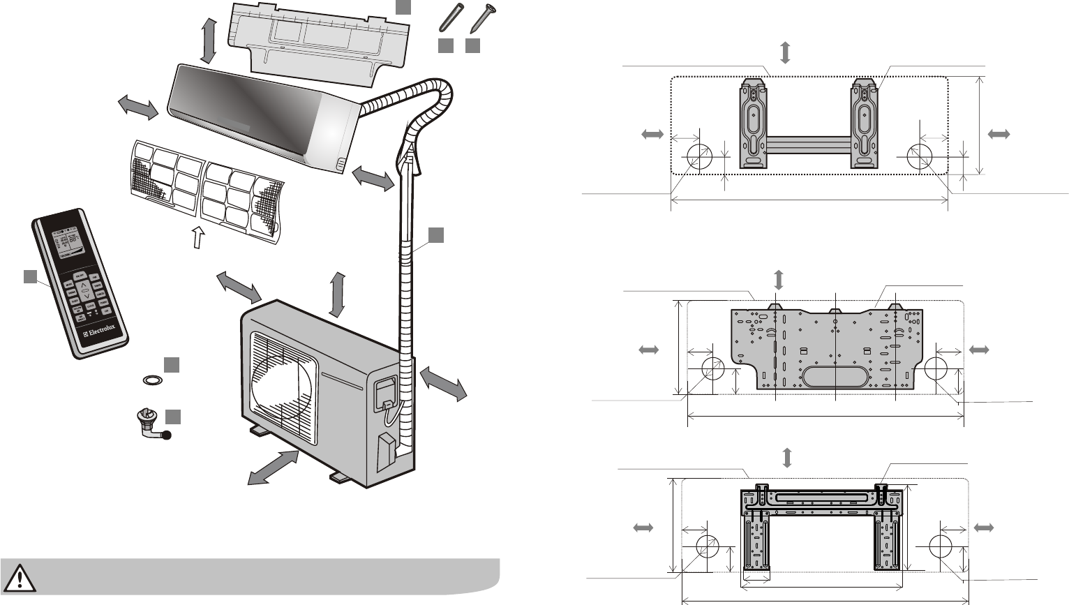
7
5
4
2
3
1
Indoor unit
Outdoor
unit
6
6
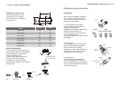
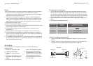
More than 12cm
More than 12cm
Air filter
More than 200cm
More than
60cm
More than 30cm
More than 60cm
More than 15cm
A
B
C
11 electrolux parts list
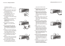
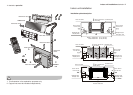
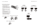
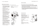
Indoor unit installation
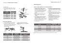
Installation plate description
indoor unit installation electrolux 12
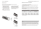
Modelos 18000 Btu’s
above 150mm from
the ceiling
Indoor unit outline
Installation plate
above 120mm
from the wall
above 120mm
from the wall
Refrigerant pipe
hole (left) Ø 65
Refrigerant pipe
hole (right) Ø 65
45
45
293
90
45
920
(A)
(B)
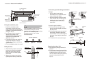
above 150mm from
the ceiling
Indoor unit outline
Installation plate
above 120mm
from the wall
above 120mm
from the wall
Refrigerant pipe
hole (left) Ø 65
Refrigerant pipe
hole (right) Ø 65
45
45
305
90
45
850
272
80
489
A
abov
15 m fr
om
e
0m
t
c
iing
he
e
l
n
ion plaI
stallat te
Indo
it
ou
e
or un tlin
bove 120m
a m
from the wall
above
120mm
om fr
the wall
R
f
ig
er
nt
pi
p
e
e
r a
h (
lef
t
Ø
6
5
o
le )
f ant piRe riger pe
(
i )
Ø
hole
rght
65
B
45
90
4
0
4
0
o s
<
12000 B (
:
710, :
25
M del
tu’
s
A B 0)
Model
12000 B
( :
790, : 26
tu’
s
A B
5)