


Eiki A-3 Movement Sensor manual. Page 3
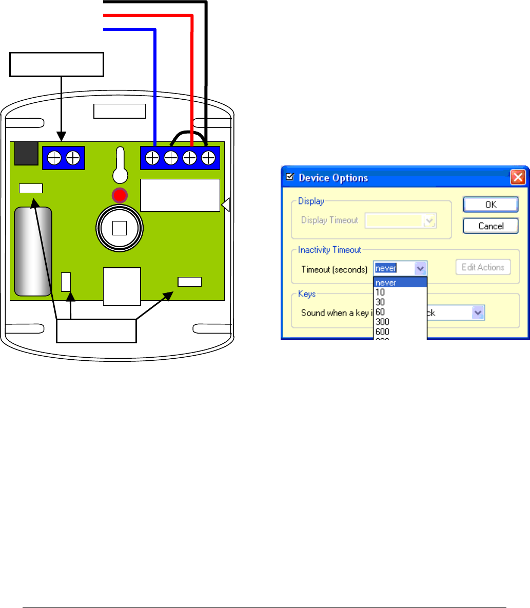
Wiring
Connect the terminals as shown in the
diagram to the control panel or access
port.
You do not need to connect the tamper
switch terminals.
Option Links
For the purpose of detecting room
occupancy, we are not as concerned
about false alarms as we would be if
this were a security system. In fact,
not detecting room movement (when
people are in the room) would be more
of a problem.
For this reason, Long Range and
Short Pulse Count links should be
fitted. Similarly, having the LED
activate is a benefit.
So for our application, fit all 3 links.
Testing
With the cover fitted, apply power and wait at
least 30 seconds. After this time, if there is
no movement, the LED should go out. Once
this has happened, any movement should
cause a couple of rapid flickers and the LED
should lock on for about 5 seconds.
Walk around the room and check that your
movement can be reliably detected. If range
seems to be inadequate, check the position of
the PCB in the base. A higher position lowers
the angle of the detection beam.
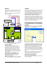
Programming your control panel
to recognise the A-3 and perform
actions
In Eiki Control System editor, select Device
Options under the Handset menu.
The Inactivity Timeout option allows you to
choose the number of seconds (up to 14400
seconds which is 240 minutes) after either
the last key is pressed or the A-3 sensor
detects movement. When that time expires
with no movement detected or key pressed,
the actions you choose under Edit Actions will
occur.
After you have selected the time, click Edit
Actions. You can treat this just like the
programming of any other key.
For more information
Please refer to the control panel’s manual for
more information.
Alarm + -
N/C 12v
GND
+12v
Sensor
Option links
Tamper switch