


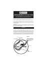
2.Screw the pattress to the ceiling after first removing the required knock
-
out and bringing the house wires through it (see figure 1). If the central
knockout is being used, seal around the wires (and the openings at the
rear ofthe pattress)with silicone orsimilar toprevent air draughtsaffecting
the smoke entering the alarm.
3.Connect thehouse wires(L -Live, N- Neutraland IC- Interconnect,if itis
being used) to the terminal block on the pattress. If an EI 161R or EI 166R
(with remote TEST/HUSH) is being installed, attach the “R” wire from the
EI 152 (see the EI 152 instructions) to the terminal marked “R” in the
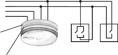
pattress (see figure1). If theEI 161R or EI 166Ris being used with aman
-
ual call point MCP400 or MCP400A then connect the R terminal to the call
point (see figures 1& 2). Otherwise do not connect anything to the ”R” ter
-
minal.
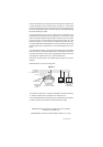
4.Connect the three wires (L, N and IC) from the pattress connector block
to the connectors on theSmoke/Heat Alarms mounting plate. Connect the
earth wire (if present) from the house wiring directly to the terminal on the
mounting plate. Replace the cover over the terminal wires.
5.Screw the mounting plate to the pattress pillars using the two screws
supplied.
6.Slide the alarm on to the mounting plate.
7.Connect the mains power – the green LED light on the alarm should be
on. When the test button is pressed the horn should sound.
If anEI 128Rpattress withrelay isbeing used,replace theEI 127Rwith the
EI 128R and follow the instructions supplied with the EI 128R.
Aico Ltd., Mile End Business Park, Maesbury Road, Oswestry,
Shropshire SY10 8NN, U.K.
EI Electronics., Shannon Industrial Estate, Shannon, Co. Clare.
R - Remote
N - Neutral
IC - Interconnect
L - Live
23
Smoke Alarm
EI 161R or EI 166R
EI 152
Manual Call Point
MCP 400
(or MCP 400A)
Pattress
EI 127R/128R
Mounting
Plate
EI 16XR
Figure 2
P/N A13894 Rev 1