


from the knockout, making sure that there is no gap when
mated with ducting/conduit. There is one suitable knockout
(the other two surface entries are not recommended as the
wiring will reduce the antenna signal). See figure 1b.
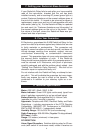
4. Screw the Ei428 module to the wall after first removing the
required knockout and bringing the house wires through it
(see figure 1b).
5. Connect the house wires (L-Live, N-Neutral) to the terminal
block as shown in figure 1b (Note the interconnect can be
hard wired to a non radio link Ei mains powered smoke alarm
(Ei141, 144, 146, 151TL, 154TL, 156TLH, 161, 161R, 164,
166, 166R) to switch the relay, if required). NB: The unit must
not be earthed so do not connect a green / yellow or copper
earth wire to any terminal.
6. Connect the wires to the required relay contacts for con-
trolling the auxiliary device. (The contacts are isolated and are
rated at 250VAC, 5 amps resistive).
2
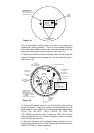
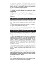
MODEL: Ei428
WARNING: DISCONNECT
MAINS BEFORE REMOVAL
RADIOLINK
RELAY
HOUSE
CODE
SWITCH
INDICATOR LIGHT
GREEN - MAINS
RED - HOUSE CODING
OR LOW BATTERY
COVER ATTACHMENT
SCREWS
Figure 1a
RECHARGEABLE
CELLS
ON/OFF
SLIDE SWITCH
HOUSE CODE
SWITCH
C - CONTINUOUS RELAY
RELAY CHANGES
FOR 5 SECONDS
P - PULSE
ANTENNA
(KEEP CABLES
AWAY)
REAR ENTRY
KNOCKOUT
INDICATOR
LIGHT
CONNECT RELAY
WIRES TO THE
TERMINAL BLOCK
NO - NORMALLY OPEN
NC - NORMALLY CLOSED
C - COMMON
(DOUBLE INSULATE ALL WIRES)
SURFACE
CONDUIT
CABLE
ENTRY
SCREW
MOUNTING
HOLES
ON
P
C
OFF
NO
N
IC
L
L
IC
N
NC
C
CONNECT MAINS
TO TERMINAL BLOCK
L - LIVE
N - NEUTRAL
(IC - INTERCONNECT
NOT NORMALLY USED)
Figure 1b