


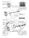
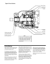
3 4 5
87
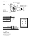
6
9 10
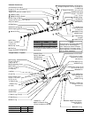
1 2
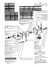
11 12 13 14 15 16 17
1
2
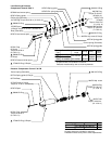
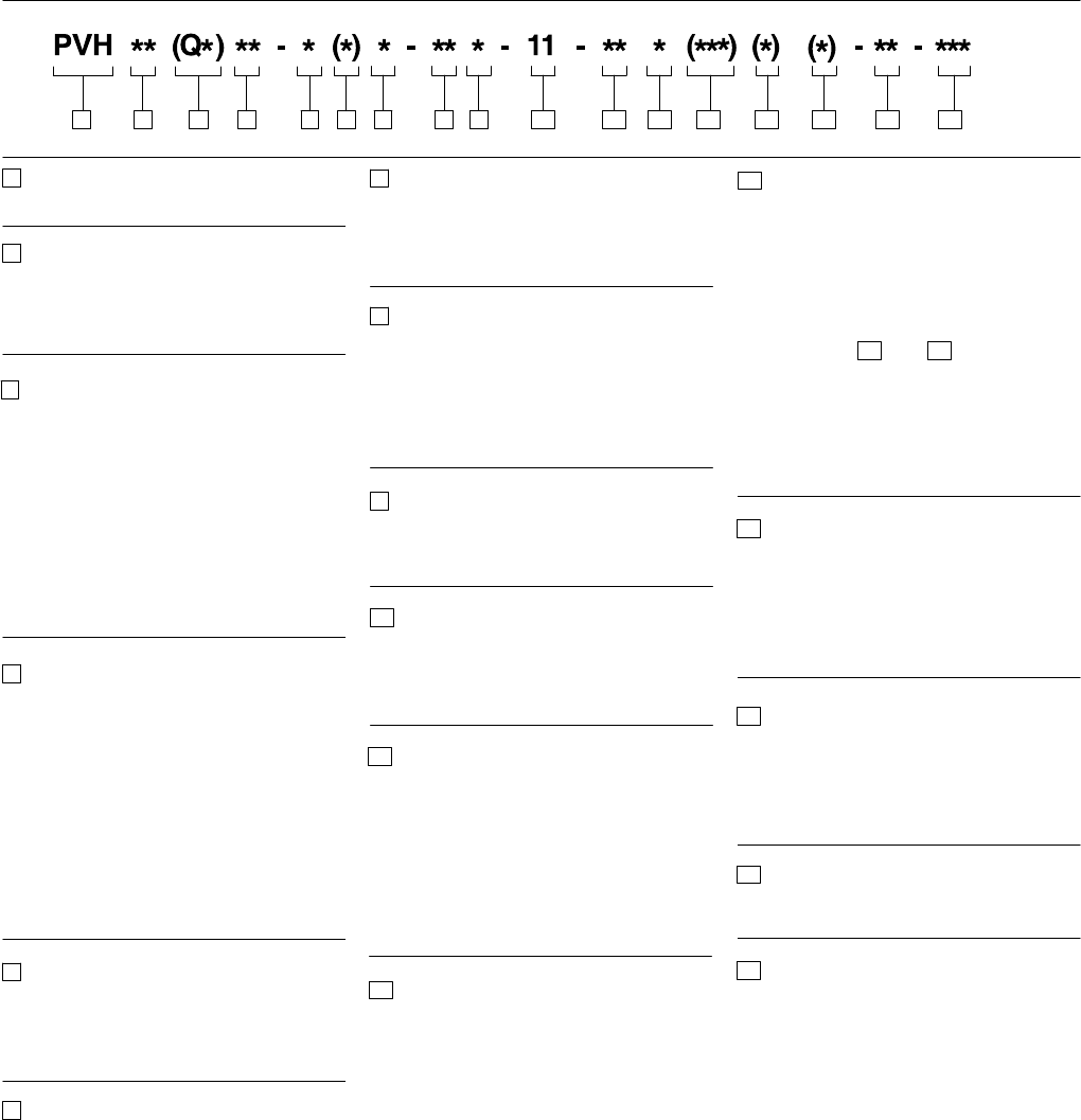
Piston pump, variable
displacement
Maximum geometric
displacement
57 - 57.4 cm
3
/r (3.5 in
3
/r)
63 - 62.9 cm
3
/r (3.84 in
3
/r)
Application style
Blank - Mobile application (rated speed
& 250/280 bar (3600-4000 psi)
pressures)
QI - Quiet industrial application (1500 -
1800 rpm & 250/280 bar
(3600-4000 psi) pressures)
QP - Quiet power unit application (1800
rpm & 140 bar (2000 psi) max.
pressures – R.H. rotation only)
Mounting flange, prime
mover end
C - SAE “C” 4–bolt type (SAE
J744-127-4 )
C2 - Optional combination 2- & 4-bolt
SAE-C pilot
C3 - Optional 4-bolt SAE-C pilot for
vertical pump mounting
M - Optional metric 4-bolt pilot ISO
3019/2-125B4HW (Must be used
with ‘N’ shaft option.)
Shaft rotation, viewed at prime
mover end
R - Right hand, clockwise
L - Left hand, counterclockwise
Configuration
Blank - Non-thru-drive (single pump)
A - SAE-A thru-drive pump, standard
(SAE J744-82-2)
B - SAE-B thru-drive pump, optional
(SAE J744-101-2/4)
C - SAE-C thru-drive pump, optional
(SAE J744-127-2/4)
S - Adjustable maximum volume
stop (‘‘S’’ option not available on
thru-drive and torque control pump
models.)
3
4
5
6
7
8
9
10
11
12
13
Main ports
F - SAE 4-bolt flange ports (standard)
M - SAE 4-bolt pads with metric
mounting bolt threads
Shaft-end type, at prime mover end
N - Metric ISO short straight key (ISO
3019/2-E32N for ‘‘M’’ pilot only)
1 - SAE-C straight key
2 - SAE-C 14 tooth spline
8 - SAE-BB, 15 tooth spline
Shaft seal, prime mover end
S - Single, one-way
D - Double, two-way
Pump design number
11 - (Subject to change. Installation
dimensions unaltered for design
numbers 10 to 19 inclusive. )
Pressure control type
C - Compensator, 140-280 bar
(2000-4000 psi)
CM - Compensator, 35-140 bar
(500-2000 psi)
IC - CETOP 3 interface compensator,
20 bar factory ‘‘differential’’ pressure
setting (QI and QP models only)
Factory compensator pressure
setting
Blank - Leave blank for ‘‘IC’’ controls only
7 - 70 bar (1015 psi) normal ‘‘CM7’’
setting (all pump sizes)
23 - 230 bar (3335 psi) normal ‘‘C23’’
setting (63, 81, 106, 141 models)
25 - 250 bar (3625 psi) normal ‘‘C25’’
setting (57, 74, 98, 131 models)
Optional pressure control
functions
Blank - Leave blank for basic compensator
controls of IC models.
V - Load sensing, 20 bar (290 psi)
factory ‘‘differential’’ pressure setting
T - Torque limiting control (Used with
sections and .
VT - Load sensing with torque limiting
VB - Load sensing with internal bleed
down (0.15” dia. orifice)
VBT- Load sensing with internal bleed
down and torque limiting
Torque limiting control pressure
setting
Blank - Leave blank if no torque limiting
control is used
4 - Standard minimum 40 bar setting of
‘‘T’’ torque control option
Torque limiting control
summation
Blank - Standard torque control
S - Optional torque control with
summation feature
Control design number
31 - All control options
Special feature suffix
031- Mounting with SAE-A, 2-bolt cover
plate
130- PVH57/63 with SAE-B, 4.00 inch
dia. pilot, 2/2-bolt mount. Both
2-bolt patterns are rotated 45
degrees from port center line.
14
15
16
17
Model Code
14
15
Printed in U.S.A.