


31
F. Performance Test of PVE
12/19/21 Piston Pump with “CG”
Compensator Control
1. Operate pump at 1200 RPM. Set remote control valve to
minimum pressure setting.
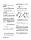
2. Refer to Figure 23 and adjust load valve (1) and globe
valve (1) to 100 PSI system pressure at P1. Observe maximum
pump flow and maximum case leakage requirement noted in
Table 4.
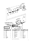
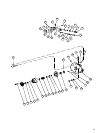
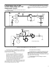
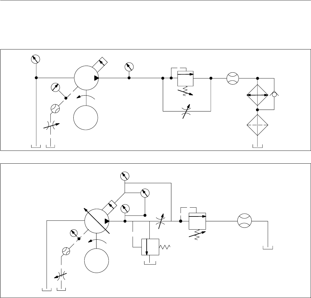
Figure 23. Circuit Diagram for “C” and “CG” Control.
Q1 Bypass
Check
Cooler
Filter
#1
V1
P1
Piston
Pump
M
P3
P2
Q2
V2
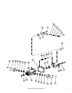
Figure 24. Circuit Diagram for “CV”, “CVP”, and “CVPC”.
Q1
#1
V1
P1
Piston
M
P3
P2
Q2
V2
P2-P1
#3
V=Flow Control Valve
Pump
3. Close load valve (1) and globe valve (1) to obtain mini-
mum pump pressure setting. Minimum pump pressure should
be approximately 250 PSI at P1.
NOTE
The ”CG” compensator is preset at the factory at
250–350 PSI. When a hydraulic line is attached
between the ”CG” compensator and remote control
valve, back pressure may exist within the hydraulic
line. As a result, the back pressure may keep the
minimum pump pressure above 350 PSI.
4. Adjust load valve (1) and remote valve to get maximum
system pressure shown in Table 5. Check pump delivery loss
and case leakage requirements from Table 5.
5. Re-adjust remote valve settings.
6. Closed load valve (1). Increase the remote control valve
setting until the pump yoke retreats to minimum stroke position.
Observe pressure at P1. Case leakage should not exceed 2
GPM. Open and close load valve (1). The pressure at P1 should
return within 50 PSI of initial setting.
7. Check the pump for external leakage. No external
leakage is permissible.