38
EATON 350 Series Dual Path Mobile Pumps E-PUPI-TS006-E September 2007
Assembly
Front Pump
Assembly
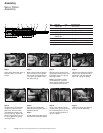
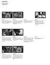
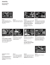
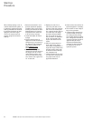
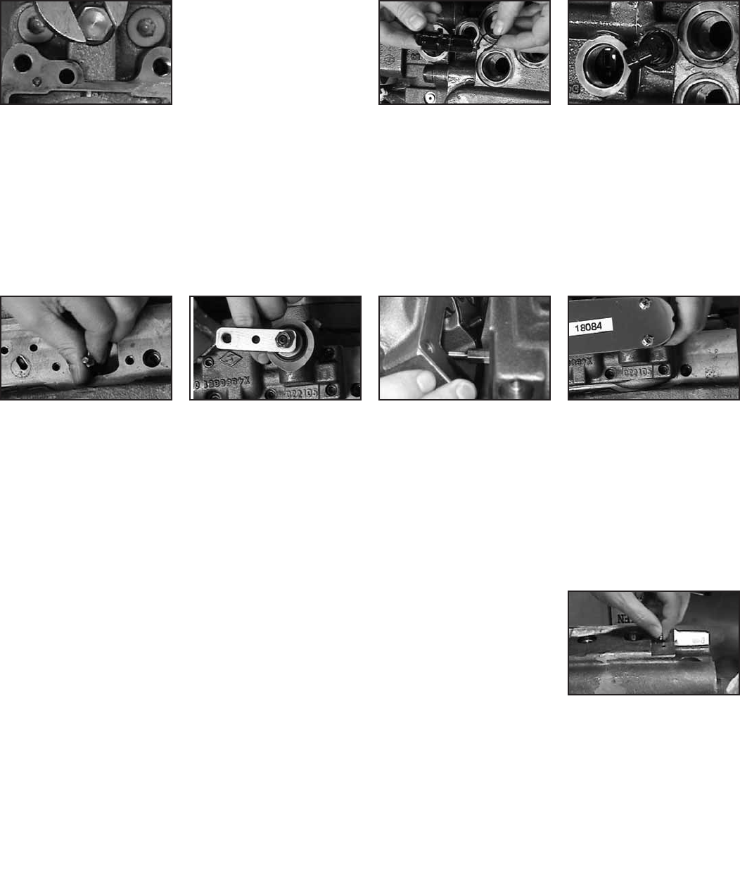
Step 37
Insert a high-pressure relief
valve in the first pressure relief
port. Tighten to 143 n/m
(105.5 lb-ft).
Step 38
Repeat process for other three
pressure relief valves and ports.
Step 39
Assemble a speed sensor: Slide
an O-Ring 4995422-001 on the
straight end of the sensor
(Refer to Item 55, page 5 for
part number), place a washer
16048-077 and snap ring
16120-125 on the plug end of
the sensor.
Step 40
Insert the sensor sub-assembly
in the speed sensor port. Using
snap-ring pliers, work the snap
ring into port until it engages
the snap ring groove.
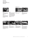
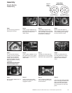
Assemble the Controller
Step 41
Insert a feedback pin 4999960-
001 through each 17mm hole
on the two controller mounting
faces. Using a 5/16-inch socket,
tighten each feedback pin to
14 n/m (10.3 lb-ft).
Step 42
Insert an M6 x 25mm socket-
head cap screw 114975-025
in each of (6) holes in the
controller housing.
Step 43
Place the controller gasket
5987239-001 over the exposed
ends of the cap screws.
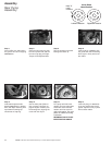
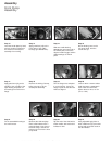
Step 44
Lift the controller housing
toward the controller mounting
face, taking care not to let the
gasket or screws fall.
Step 45
Align the feedback link inside
the controller housing with the
feedback pin extending from the
mounting plate. Tighten the
screws to 14 n/m (10.3 lb-ft).
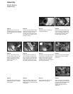
Displacement Limiters
Step 46
If the pump includes displace-
ment limit ports, insert a
displacement limiting screw
16139-644 in each of the two
larger ports.
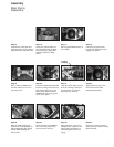
Step 47
Install a sealing nut 5996839-
001 over each displacement
limiting screw and tighten to
16 n/m (11.8 lb-ft).
Step 48
Repeat this process for the two
smaller displacement limit ports,
tightening the sealing nuts
5996838-001 to 9 n/m (6.6 lb-ft).
Step 49
Seal unused ports with appro-
priate plugs.


