


6
1.3.1 Reduced clearances using shielding
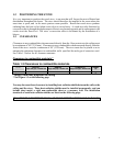
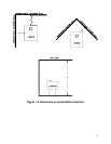
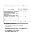
You may decrease the minimum clearances to combustible materials by installing heat radiation
shields between the walls or the ceiling and the stove. Those heat radiation shields must be installed
permanently, and must be made of a heat-resistant or heat-tolerant material. Consult the table below:
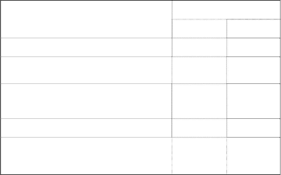
Reducing Clearances With
Shielding
TYPE OF PROTECTION
Sides and
Rear/Back
Top
Sheet metal, a minimum of 0,013" (0,33 mm) spaced out at
least 7/8" (21 mm) by non-combustible spacers.
67% 50%
Ceramic tiles, or an equivalent non-combustible material on
fire-proof supports spaced out at least 7/8" (21 mm) by non-
combustible spacers.
50% 33%
Ceramic tiles, or an equivalent non-combustible material on
fire-proof supports with a minimum of 0,013" (0,33 mm)
sheet metal backing spaced out at least 7/8" (21 mm) by non-
combustible spacers.
67% 50%
Brick spaced out at least 7/8" (21 mm) by non-combustible
spacers.
50% N/A
Brick with a minimum of 0,013" (0,33 mm) sheet metal
backing spaced out at least 7/8" (21 mm) by non-
combustible spacers.
67% N/A
Source: CSA Standard B365-1991, Table 4, Page 27
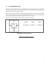
Convert specification to R-value:
k-factor is given with a required thickness (T) in inches: R=1/k x T
C-factor is given: R=1/C
Example:
If the floor protector is 4” brick with a C-factor of 1.25 over 1/8” mineral board with
a k factor of 0.29 the total R-value of the system is:
4” brick C=1.25, R=1/1.25=0.8
1/8” mineral board K=0.29, R=1/0.29 x 0.125=0.431
Total R = Rbrick + Rmineral = 0.8 + 0.431 = 1.231
Total R is greater than 1.0, the system is acceptable.