


14
REDUCED CLEARANCES
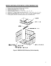
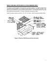
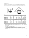
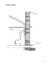
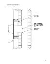
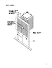
You may decrease the clearances by installing heat radiation shields between the walls or
the ceiling and the stove. These heat radiation shields must be installed permanently, and
can include sheet metal, a rigid non-combustible sheet or a masonry wall.
Clearances of not less than 1" (25 mm) and not more than 3" (76 mm) between the bottom
of the shield and the floor and not less than 3" (76 mm) between the top of the shield and
the ceiling must be respected to allow vertical air circulation behind the shield.
The shield must extend 20" (500 mm) above the stove top and 18" (450mm) to each side
of the stove.
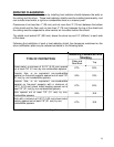
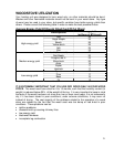
Following the installation of such a heat radiation shield, the clearances mentioned on the
stove certification plate may be reduced as stated in the following table.
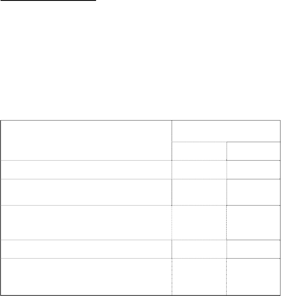
Reducing Clearances With
Shielding
TYPE OF PROTECTION
Sides and
Rear/Back
Top
Sheet metal, a minimum of 0,013" (0,33 mm) spaced
out at least 7/8" (21 mm) by non-combustible spacers.
67% 50%
Ceramic tiles, or an equivalent non-combustible
material on fire-proof supports spaced out at least 7/8"
(21 mm) by non-combustible spacers.
50% 33%
Ceramic tiles, or an equivalent non-combustible
material on fire-proof supports with a minimum of
0,013" (0,33 mm) sheet metal backing spaced out at
least 7/8" (21 mm) by non-combustible spacers.
67% 50%
Brick spaced out at least 7/8" (21 mm) by non-
combustible spacers.
50% N/A
Brick with a minimum of 0,013" (0,33 mm) sheet metal
backing spaced out at least 7/8" (21 mm) by non-
combustible spacers.
67% N/A
Source: CSA Standard B365-1991, Table 4, Page 27