


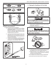
620515, 620525, 620526, 630515 & 630516 Installation Instructions
13
If bolts are left loose there may not be ad-
equate roof seal or if over tightened, damage
may occur to the air conditioner base or ceil-
ing template. Tighten to specifications listed
in this manual.
CAUTION
Improper installation and sealing of foam di-
vider will cause the compressor to quick cycle
on the cold control. This may result in fuse or
circuit breaker opening and/or lack of cool-
ing.
CAUTION
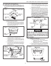
• Place the foam divider in the return air open-
ing above the center duct before installing
ceiling template.
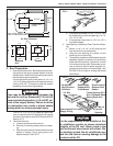
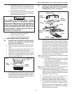
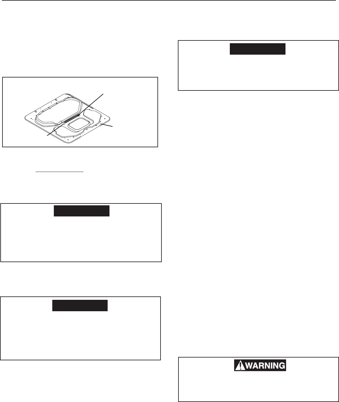
c. Install Ceiling Template
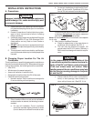
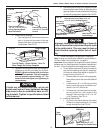
• Apply a piece of foam weather stripping (not
supplied) to the upper side of ceiling tem-
plate to make a seal between it and the
duct. Use a soft piece of foam weather strip
1 x 3/4 x 10 inches. See FIG. 24.
d. Start each mounting bolt through the ceiling tem-
plate and up into the unit base pan by hand.
EVENLY tighten the three bolts to a torque
of 40 to 50 inch pounds. This will compress
the roof gasket to approximately 1/2". The
bolts are self locking so over tightening is
not necessary.
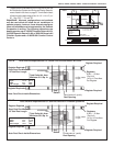
e. Use Aluminum foil tape (not supplied) to seal
the ends of the foam divider to the sides of the
opening. Make sure the area behind the flange
on the ceiling template is sealed. See FIG. 22.
f. Cut the opening in the center duct using the
discharge opening in the ceiling template for a
pattern. Seal the center duct to the ceiling tem-
plate using foil tape, foam insulation or silicon
sealant.
CAUTION
Disconnect the positive (+) 12 volt DC termi-
nal at the supply battery. Damage to equip-
ment could occur if the 12 volt DC is not shut
off.
H. Wiring The System
Reach up into the return air opening and pull the re-
maining wires down.
1. Connection Of Low Voltage Wires
Note: If solar panel is installed see instructions packaged
with solar panel option.
Note: If using the Genesis Air Filtration System step "b" is
to be completed when installing the decorative cover.
a. Route Remote Temperature Sensor cable, if
applicable, and attach it to the connector that
matches its color in the control box.
b. Connect the previously run 12 VDC to the red
and black wires protruding from the control box.
(In multiple zone installations, this needs to be
done at only one zone.) Connect +12 VDC to
the red wire; –12 VDC to the black wire.
c. Connect the previously run furnace thermostat
wires (if applicable) to the blue wires protruding
from the control box. The polarity of these
connections does not matter.
d. Connect the previously run Energy Manage-
ment System wires (if applicable) to the yellow
wires protruding from the control box. The polar-
ity of these connections does not matter.
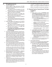
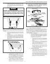
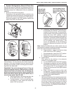
e. Terminate the 4-conductor control cable(s) pro-
truding into the 14-1/4" x 14-1/4" (±1/8") roof
opening. The cable(s) must be terminated with
a telephone RJ-11-6C4P connector. Refer to the
crimp tool manufacturer for crimping instruc-
tions.
Important: RJ-11-6C4P connectors must be installed
as shown in FIG. 8A, 8B & 8C.
f. Plug the control cable(s) into the telephone
jack(s) on the control box. (It does not matter
which one.)
g. Locate the ambient sensor plug coming from
the unit, and attach it to the connector that
matches its color in the control box.
2. Connection Of 120 Volt Power Supply
Disconnect 120 volt AC. Failure to follow these
instructions could create a shock hazard
causing death or severe personal injury.
FIG. 24
Stick Weather Strip To Top
Of Ceiling Template
Weather Strip
Ceiling
Template