


7
Replace the top decoration panel. Be careful not to pinch
the wires behind the panel.
Make sure the tabs snap back into the holes in the hinge
plate.
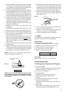
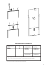
STEP 3: Two screws installed in the rear base.
See FIG. 10.
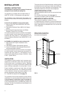
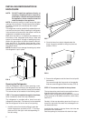
Failure to follow the sequence in securing the refrigerator
in the enclosure can cause leakage between the frame
and cabinet. Any space between the counter, storage
area or ceiling and top of the refrigerator greater than 1-
1/2 inches should be blocked. The heat produced at the
rear of the refrigerator will become trapped in this space,
making the top of the refrigerator hot and reduce the
efficiency of the refrigerator.
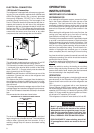
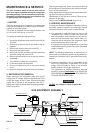
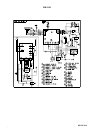
GAS CONNECTION
Hook up to the gas supply line is accomplished at the
manual gas valve, which is furnished with a 3/8" SAE
(UNF 5/8" -18) male flare connection. All completed con-
nections should be checked for leaks with soapy water.
FIG. 9
DO NOT use a flame to check for gas leaks.
The gas supply system must incorporate a pressure
regulator to maintain a supply pressure of not more than
11 inches water column.
When testing the gas supply system at test pressures in
excess of 1/2 psi, the refrigerator and its individual shutoff
valve must be disconnected from the gas supply piping
system.
When testing the gas supply system at pressures less
than or equal to 1/2 psi, the appliance must be isolated
from the gas supply piping system by closing its indi-
vidual manual shutoff valve.
In case detailed instructions on the installation and con-
nection to the gas supply are required, contact your
dealer or distributor.
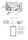
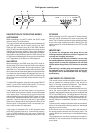
TESTING LP GAS SAFETY SHUTOFF
The gas safety shutoff must be tested after the re-
frigerator is connected to the LP gas supply.
To test the gas safety shutoff, proceed as follows:
1. Start the refrigerator and switch to GAS mode.
(See start up instructions).
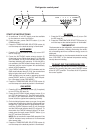
2. Check that the gas flame is lit and the GAS mode
indicator lamp (C) is on.
3. Close the manual gas shutoff valve at the back of
the refrigerator. (See FIG. 1).
4. Wait for one minute. The CHECK indicator lamp (E)
should be on and the GAS mode indicator lamp (C)
should be off.
5. Remove protection cover (see FIG. 1) and open
the manual gas shutoff valve. Do not change any
button positions on the control panel. Apply a non-
corrosive commercial bubble solution to the burner
jet orifice.
6. No bubbles should appear at the opening of the
burner jet orifice. The presence of bubbles indi-
cates a defective gas safety shutoff, and service is
required.
7. If no bubbles were present at the burner jet orifice,
it should be rinsed with fresh water. Be careful not
to damage the burner jet orifice. Replace cover and
press the main power ON/OFF button (1) OFF and
back ON. Normal operation of the burner should
return. Allow the burner to operate for a minimum
of 5 minutes.
1
2
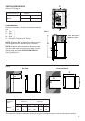
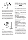
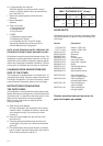
Drain water hose
A hole must be drilled through flooring see FIG. 10.
The installer MUST make sure that the hose does not
kink when run through the floor. Seal around the hose
that goes through the drilled hole. If a longer hose than
supplied is required to get the water to drain outside of
the vehicle, the installer will have to supply the extra
length of hose.
! WARNING
FIG. 10
Hole for drain water hose