


INSTALLATION INSTRUCTIONS
8
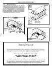
It is the responsibility of the installer to en-
sure the duct work will not collapse or bend
during and after installation. Dometic Corpo-
ration will not be liable for any structural dam-
age due to improperly insulated, sealed or
collapsed duct work.
CAUTION
Dometic Corporation will not be held liable
for roof structural or ceiling damage if the
duct work is not adequately wrapped in an
insulation blanket.
CAUTION
2.3.1 COOLING REQUIREMENTS
When determining the cooling requirements of each vehicle,
the following should be considered:
A. The size of the vehicle will determine the number of
air conditioning units that are required, or the need
to pre-wire for additional air conditioners depending
on the geographical location of use.
B. Amount of insulation in walls, floor and roof of the
vehicle.
C. Identify possible heat sources and plan accordingly:
1. Skylights - location should not be within 4 feet of
the air conditioner return system.
2. Skylights - should be tinted and double pane.
3. Roof vents should be a tinted type, and quan-
tity kept to minimum.
4. Increased use of slide-outs and/or glass square
footage will require tinting with additional
insulation in wall and ceiling cavities.
5. Calculation of heat producing appliances.
2.3.2 AIR DISTRIBUTION SYSTEM SIZING
Basement systems are designed exclusively with external
ductwork for the cold air discharge. There are not provi-
sions for an electric heater to be installed as part of the
unit. The central furnace will supply heating of the
vehicle, if installed.
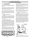
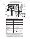
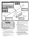
The condenser section must be installed so as to have direct
access to the outside ambient. Removal of the heated
condenser air is critical for proper operation.
The installer of this air conditioner must design the air
distribution system for his particular application by following
the guidelines specified within this application manual and
unit installation instructions. Several specific requirements
MUST BE met for the air conditioner to operate correctly:
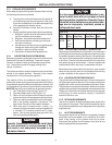
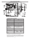
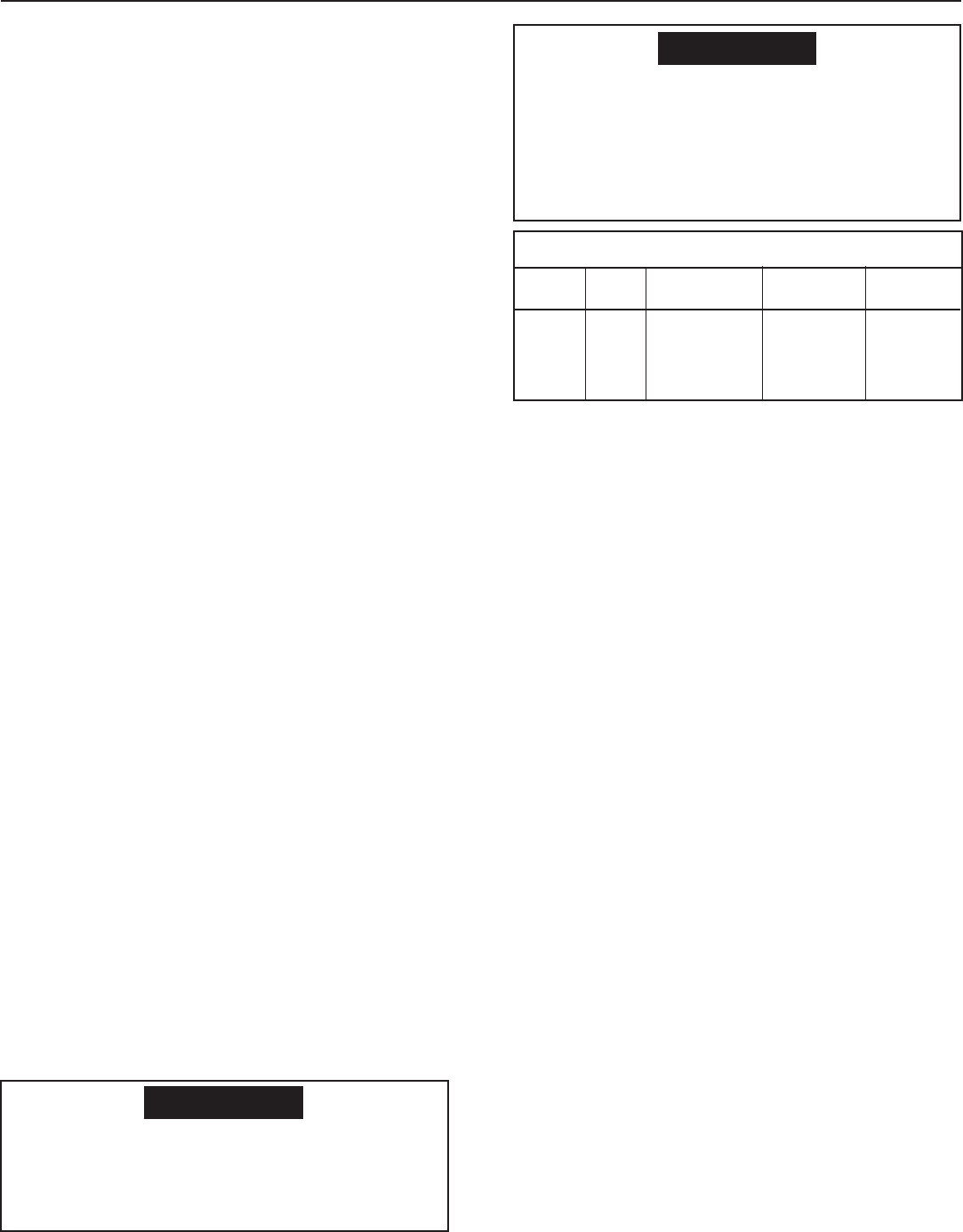
1. Unit Total Static Pressure See Figure 2.10.
2. Duct Area Requirement. See Figure 2.10.
3. Return air to the system must be filtered to prevent
dirt accumulation on the evaporator cooling surface.
4. Return air opening must be within minimums speci-
fied in the system installation instructions. This
figure must include the filter material selected.
5. Since duct work is located within a cavity, it is
necessary that all duct work must be wrapped with
a minimum R7 insulating blanket with a vapor
barrier. This will help prevent heat gain within the
duct and possible condensation.
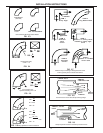
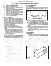
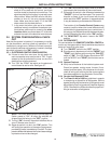
2.3.3 AIR DISTRIBUTION DUCT PREPARATION
Depending on the distribution configuration, ensure that the
air entry points have the minimum square inches required for
the series of system installed. See Figure 3.4 for permissible
duct layout. Duct elbows and/or restrictions must be kept to
a minimum. The duct must be pre-built within the structure
and sealed along its entire length. If joints or bends leak
conditioned air within the cavity, condensation will form.
When the duct is installed within the structure, care must be
taken to insure that the duct will not collapse or bend during
or after installation of the system to the vehicle.
2.3.4 LOCATION OF DISTRIBUTION DUCT
The vehicle itself and the placement of interior components
will dictate the location of the duct. One must be sure that the
registers will not fall near the thermostat or the return filters.
The placement must be such that the air distribution from the
registers will provide the best possible movement within the
living area. Calculations should be made as to the strength
of the cavity, to insure structural integrity if notched for
location of the duct runs.
2.3.5 RETURN REQUIREMENTS
The return air system must be considered when layout of the
duct system is in process. This should be located as near to
the system as possible to insure adequate return back to the
evaporator coil.
2.4 HI-POT REQUIREMENTS
Each system that is built by Dometic is completely checked
electrically and hi-pot tested on our production line. Addi-
tional hi-pot testing of the system must not be done.
Disconnect the system from the power circuit prior to any
vehicle high potential test operations.
System Duct Condenser Evap. Static
P/N Size Inlet Req. Inlet Req. Press
39626 3x15" 648 in
2
135 in
2
0.40 - 1.20
39726 min.
5x16"
max.
FIG. 2.10