


P83848 A
Sheet 6 of 7
CAUTION: Check that the installed product will have sufficient clearance and wiring room prior to installing backboxes and
conduit, especially if sheathed multiconductor cable or 3/4" conduit fittings are used.
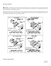
1. Audible Horn Strobe models have an integrated 823 Mounting Plate.
2. The 823 Mounting Plate must be oriented correctly when it is mounted to the backbox. Turn the 823 Mounting Plate so that the
arrow below the word “Top” points to the top side of the 823 Mounting Plate.
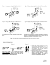
3. Audible Horn Strobe models can be flush mounted to a standard single-gang backbox (Figure A), 4” or 100mm backbox (Figure
B) or double-gang backbox (Figure C). Audible Horn Strobe models can also be surface mounted to a 4” or 100mm backbox
(Figure B), double-gang backbox (Figure C) or the SHBB (Figure D).
4. Mount the 823 Mounting Plate first to the backbox. Next slide the 823 Beauty Plate over the 823 Mounting Plate until the 2 side
snaps of the 823 Beauty Plate engage with the 823 Mounting Plate.
5. The 823 Beauty Plate can be removed from the strobe assembly once engaged. First, gently insert a screwdriver into one of the
slots located on the side edges of the Audible Horn Strobe Beauty Plate. Second, gently pull away from the wall with the inserted
screwdriver to disengage the snap. Third, repeat the first and second steps for the second slot. Finally, gently lift the 823 Beauty
Plate away from the 823 Mounting Plate.
6. Mounting hardware for each mounting option is supplied.
7. Conduit entrances to the backbox should be selected to provide sufficient wiring clearance for the installed product.
8. When terminating field wires, do not use more lead length than required. Excess lead length could result in insufficient wiring
space for the signaling appliance.
9. Use care and proper techniques to position the field wires in the backbox so that they use minimum space and produce minimum
stress on the product. This is especially important for stiff, heavy gauge wires and wires with thick insulation or sheathing.
10. Do not pass additional wires (used for other than the signaling appliance) through the backbox. Such additional wires could
result in insufficient wiring space for the signaling appliance.
CAUTION: If these appliances are operated within 15 inches of a person's ear, they can produce a sound pressure level that
exceeds the maximum 120dBA permitted by ADA and OSHA rules. Exposure to such sound levels can result in damage to a person's
hearing.
FIELD OF VIEW, UNDER CERTAIN CIRCUMSTANCES, MIGHT INDUCE A PHOTO-SENSITIVE RESPONSE IN
PERSONS WITH EPILEPSY. STROBE REFLECTIONS IN A GLASS OR MIRRORED SURFACE MIGHT ALSO
INDUCE SUCH A RESPONSE. TO MINIMIZE THIS POSSIBLE HAZARD, DMP STRONGLY RECOMMENDS THAT
THE STROBES INSTALLED SHOULD NOT PRESENT A COMPOSITE FLASH RATE IN THE FIELD OF VIEW
WHICH EXCEEDS FIVE (5) Hz AT THE OPERATING VOLTAGE OF THE STROBES. DMP ALSO STRONGLY
RECOMMENDS THAT THE INTENSITY AND COMPOSITE FLASH RATE OF INSTALLED STROBES COMPLY
WITH LEVELS ESTABLISHED BY APPLICABLE LAWS, STANDARDS, REGULATIONS, CODES AND GUIDELINES.
NOTE: NFPA 72/ANSI 117.1 conform to ADAAG Equivalent Facilitation Guidelines in using fewer, higher intensity strobes within
the same protected area.
CAUTION: Check the installation instructions of the manufacturers of other equipment used in the system for any guidelines or
restrictions on wiring and/or locating Notification Appliance Circuits (NAC) and notification appliances. Some system communication
circuits and/or audio circuits, for example, may require special precautions to assure electrical noise immunity (e.g. audio crosstalk).
NOTE: This equipment has been tested and found to comply with the limits for a Class B digital appliance, pursuant to Part 15 of the
FCC Rules. These limits are designed to provide reasonable protection against harmful interference in residential installation. This
equipment generates, uses and can radiate radio frequency energy and, if not installed and used in accordance with the instructions,
may cause harmful interference to radio communications. However, there is no guarantee that interference will not occur in a
particular installation. If this equipment does cause harmful interference to radio or television reception, which can be determined by
turning the equipment off and on, the user is encouraged to try to correct the interference by one or more of the following measures: 1)
Reorient or relocate the receiving antenna, 2) Increase the separation between the equipment and receiver, 3) Connect the equipment
into an outlet on a circuit different from that to which the receiver is connected, and 4) Consult the dealer or an experienced radio/TV
technician for help.