


www.dimplex.de E-5
English
7.4
7 Installation
7.1 General Information
The following connections need to be established on the heat
pump:
Flow and return flow of the brine system
Flow and return flow of the heating system
Power supply
7.2 Heating System Connection
ATTENTION!
Flush the heating system prior to connecting the heat pump.
Before connecting the heating water system to the heat pump,
the heating system must be flushed to remove any impurities,
residue from sealants, etc. Any accumulation of deposits in the
liquifier could cause the heat pump to completely break down.
Once the heating system has been installed, it must be filled, de-
aerated and pressure-tested.
The sensors which are delivered already connected and loosely
placed in the switch box must be mounted and insulated accord-
ing to the block diagram.
Minimum heating water flow rate
The minimum heating water flow rate through the heat pump
must be assured in all operating states of the heating system.
This can be accomplished, for example, by installing either a
manifold without differential pressure or an overflow valve. The
procedure for adjusting an overflow valve is described in the
Chapter Start-Up.
Antifreeze protection for installation locations
prone to frost
The antifreeze function of the heat pump controller is active
whenever the controller and the heat circulating pumps are ready
for operation. If the heat pump is taken out of service or in the
event of a power failure, the system has to be drained. The heat-
ing circuit should be operated with a suitable antifreeze if heat
pump systems are implemented in buildings where a power fail-
ure can not be detected (holiday home).
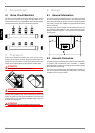
7.3 Heat Source Connection
The following procedure must be observed when connecting the
heat source:
Connect the brine pipe to the heat pump flow and return. The hy-
draulic plumbing diagram must be adhered to.
ATTENTION!
The supplied dirt trap must be inserted in the heat source inlet of the heat
pump to protect the evaporator against the ingress of impurities.
In addition, a micro bubble air separator must be installed in the
heat source system.
The brine liquid must be produced prior to charging the system.
The liquid must have an antifreeze concentration of at least 25 %
to ensure frost protection down to -14 °C.
Only monoethylene glycol or propylene glycol-based antifreeze
may be used.
The heat source system must be de-aerated and checked for
leaks.
ATTENTION!
The brine solution must contain at least a 25 % concentration of a
monoethylene glycol or propylene glycol-based antifreeze, which must
be mixed before filling.
7.4 Electrical Connection
The following electrical connections must be established on the
heat pump:
Connection of the control line to the control panel of the heat
pump via terminal X1: L/N/PE.
Connection of the mains cable to the control panel of the
heat pump via terminal X6: L/N//PE.
Connection of the brine circulating pump (to be provided by
the customer) to the control panel of the heat pump via ter-
minal X1: PE and pump contactor K5: 2/4. As an option, the
brine pump can also be directly connected (see terminal
connection plan).
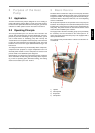
All electrical components required for the operation of the heat
pump are located on the control panel.
For detailed instructions concerning the connection and function-
ing of the heat pump controller (e.g. external wall sensor included
in the scope of supply) refer to the operating manual supplied
with the controller.
An disconnecting device with a contact gap of at least 3 mm (e.g.
utility blocking contactor or power contactor) as well as a 1-pole
circuit breaker have to be provided by the customer. The re-
quired conductor cross section is to be selected according to the
power consumption of the heat pump, the technical connection
requirements of the respective utility company as well as all ap-
plicable regulations. Details on the power consumption of the
heat pump are listed on both the product information sheet and
the type plate. The connection terminals are designed for a max.
conductor cross section of 10 mm².