


MIR40 Log Stove
IMPORTANT: THESE INSTRUCTIONS SHOULD BE READ CAREFULLY AND RETAINED FOR FUTURE REFERENCE
Important Safety Advice
When using electrical appliances, basic precautions should
always be followed to reduce the risk of fire, electrical shock,
and injury to persons, including the following:
If the appliance is damaged, check with the supplier before
installation and operation.
Leave the appliance disconnected from the supply voltage until
it is commissioned.
Do not use this heater in the immediate surroundings of a bath,
shower or swimming pool.
Do not locate the heater immediately below a fixed socket outlet
or connection box.
Do not cover or obstruct in any way the heat outlet grille located
at the top of the heater or the heat outlet at the base of the
heater. Overheating will result if the heater is accidentally
covered.
This appliance is not intended for use by children or other
persons without assistance or supervision if their physical,
sensory or mental capabilities prevent them from using it safely.
Children should be supervised to ensure that they do not play
with the appliance.
In the event of a fault unplug the heater.
Unplug the heater when not required for long periods.
Ensure that furniture, curtains or other combustible material
are positioned no closer than 1 metre from the heater.
Although this heater complies with safety standards, we do not
recommend its use on deep pile carpets or on long hair type of
rugs.
The appliance must be positioned so that the plug is accessible.
If the supply cord is damaged it must be replaced by the
manufacturer or service agent or a similarly qualified person in
order to avoid a hazard.
General
This fire incorporates a flame effect that can be used without heating,
so that the comforting effect may be enjoyed at any time of the year.
The flame effect is provided by a low wattage motor and two 60 watt
lamps. Using the flame effect on it’s own, therefore, requires little
electricity.
The fan assisted hot water convector heater (heat exchanger) is located
at the base of the fire. A separate 2kW electric heating unit is concealed
behind the top grill. The electric heating unit can be used separately
from the heat exchanger as an individual heat supply when the central
heating system is not on. It may also be used as a heat boost when
using the heat exchanger (central heating system on).
Heat Exchanger
The MIR40 Log Stove may be fitted in place of or in addition to existing
radiators. Using the hot water from the central heating system and a
powerful electric fan it will produce up to 2.0kW of heat into the room.
The heat output from the heat exchanger unit may be adjusted by means
of a variable speed fan.
Electrical
WARNING – THIS APPLIANCE MUST BE EARTHED
This heater must be used on an AC ~ supply only and the voltage marked
on the heater must correspond to the supply voltage.
Before switching on, please read the safety warnings and operating
instructions.
For your convenience, the heater is fitted with a rewireable plug
incorporating a 13 amp fuse. In the event of replacing the fuse in the
plug supplied, a 13 amp fuse approved by ASTA to BS1362 must be
used.
Central Heating System Design
1. When fitting the MIR40 Log Stove on to a central heating system
check that the boiler is capable of delivering the extra heat into the
appliance by re-sizing the system. The MIR40 will add under ideal
conditions 2.0kW (6,800 Btu/hr) onto the boiler sizing.
2. Due to the low water content of the heat exchanger in the MIR40
Log Stove compared to a panel radiator in the system, an adequate
flow of water should be maintained to compensate for rapid cooling
of the water as it passes through the exchanger i.e. maximum
efficiency is gained if the MIR40 Log Stove is placed as near to the
central heating pump as possible to give the maximum pressure
head across the appliance.
3. To prevent cold air from being blown into the room a low limit
thermostat is fitted which prevents the fan starting until hot water
reaches the heat exchanger. This principle must be explained to
the user to prevent any confusion arising over the appliance’s
operation.
Installation
Ensure that all packing items are removed (read any warning labels
carefully).
Retain the packaging for possible future use, in the event of moving or
returning the fire to your supplier.
The MIR40 Log Stove is designed either;
1. To be installed into an inset cavity. When installing into an inset
cavity, ensure that there is an adequate unobstructed air intake
available to the air inlet slots located at the back of the appliance.
Both the heat exchanger fan and the electric heater fan require an
adequate supply of air for their effecient operation.
2. To be floor mounted, preferably on a hearth. For stability, keyhole
slots are provided in the back panel for wall fixing.
The appliance should not be placed where it could be moved or knocked
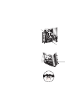
by doors etc. If installing the appliance into an inset cavity, or if using a
fire surround in conjunction with the MIR40, the minimum clearance
dimensions shown in Fig. 1 must be observed.
The wall mounting dimensions are shown in Fig. 2.
Note: The switch ‘a’ in Fig. 2 is for factory test purposes only and access
is not required after installation.
Water connections
WARNING : Do not connect to electricity supply when making water
connections.
The appliance terminates in 10mm pipe tails (top pipe for return - see ‘b’
in Fig. 4 and bottom pipe for flow - see ‘c’ in Fig. 4).
It will be neccessary to make up a 10mm pipe connection which will join
up the existing water system to the appliance pipe tails.
We recommend the use of ‘Nevacock’ ball valves or other types of gate
valve as close as possible to the appliance.
To remove the surround , first remove 8 outer screws from surround
and 2 screws from inside door (see Fig. 3) and place carefully aside.
Gently slide the surround away from the chassis.
After connecting the appliance to the heating circuit refill the system (if
required) and bleed the air out of the heat exchanger using the bleed
screw provided (located on top of return pipe - see ‘a’ in Fig. 4). If any
water escapes from the bleed screw ensure that it does not fall onto any
electrical wiring or connections. After bleeding the appliance ensure
that electrical controls are completely dry before connecting to the supply.
NOTE : PLEASE ENSURE THAT NO WATER IS IN CONTACT WITH
THE MDF BASE OF THE STOVE.
Commissioning the Heat Exchanger
Ensure that the central heating is OFF and that the heat exchanger
is COLD.
1. Check the appliance for water leaks at every connection, bleed
screw etc. Ensure the electrical circuit is free from water.
2. Replace the surround and screw (10 screws) fix to chassis.
3. Turn ON electricity supply.
4. Press ‘Switch 1’ to ’ ’. The flame effect should now operate - see
Fig. 7.
5. Press ‘Switch 4’ to the large Fan symbol. The fan should not start
due to the low limit thermostat.