


E-6
English
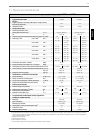
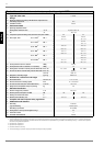
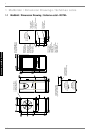
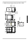
6.3
The values in parentheses are valid for the LI 24TEL/ LI 28TEL
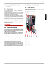
6.3 Heating System Connection
The heating system connections on the heat pump have a 1 1/4"
external thread. Use a spanner to firmly grip the transitions when
connecting the heat pump.
Before connecting the heating water system to the heat pump,
the heating system must be flushed to remove any impurities,
residue from sealants, etc. Any accumulation of deposits in the
liquifier could cause the heat pump to completely break down.
For systems in which the heating water flow can be shut off via
the radiator or thermostat valves, an overflow valve must be in-
stalled in a heating bypass behind the heat pump by the cus-
tomer. This ensures a minimum heating water flow rate through
the heat pump and helps to avoid faults.
Once the heating system has been installed, it must be filled, de-
aerated and pressure-tested.
Minimum heating water flow rate
The minimum heating water flow rate through the heat pump
must be assured in all operating states of the heating system.
This can be accomplished, for example, by installing either a
manifold without differential pressure or an overflow valve. The
procedure for adjusting an overflow valve is described in the
Chapter Start-Up.
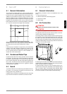
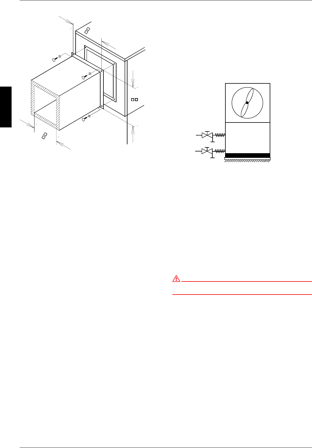
Antifreeze
A method of manual drainage (see illustration) should be pro-
vided for heat pumps which are exposed to frost. The antifreeze
function of the heat pump controller is active whenever the con-
troller and the heat circulating pump are ready for operation. If
the heat pump is taken out of service or in the event of a power
failure, the system has to be drained. The heating circuit should
be operated with a suitable antifreeze if heat pump systems are
implemented in buildings where a power failure can not be de-
tected (holiday home).
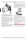
6.4 Electrical Connection
The power supply and control voltage are supplied using stand-
ard cables (load: 4-core, control: 3-core).
For detailed instructions on how to connect the external compo-
nents and how the heat pump controller functions, please refer to
the device connection diagram and the operating manual sup-
plied with the controller.
An all-pole disconnecting device with a contact gap of at least
3 mm (e.g. utility blocking contactor or power contactor) as well
as a 3-pole circuit breaker with common tripping for all external
conductors must be installed in the power supply (tripping current
in compliance with the Device Information).
Ensure that the incoming supply has a clockwise rotating field
when connecting multiphase devices L1; L2; L3.
ATTENTION!
Ensure that there is a clockwise rotating field: Operating the compressor
in the wrong rotational direction could cause damage to the compressor.
The control voltage must be protected by a 10 A fuse.
For detailed information, see Circuit Diagrams in the Appendix.
P
L
Q
P
L
Q
0[
P
D
[
P
D
[