


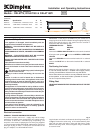
Dimensions
(millimetres)
Installation and Operating Instructions
Dimplex Skirting Heaters
Models : DXLAT75, DXLAT150 & DXLAT150Ti
INDCLTS7RG Issue 1
Models Specification A B
DXLAT75 0.75kW Switch / Thermostat / Neon 250 120
DXLAT150 1.5kW Switch / Thermostat / Neon 305 165
DXLAT150Ti 1.5kW 24Hour Timer / Thermostat 305 165
IMPORTANT : THESE INSTRUCTIONS SHOULD BE READ CAREFULLY AND RETAINED FOR FUTURE REFERENCE
Important Safety Advice
If the appliance is damaged, check immediately with the
supplier before installation and operation.
WARNING – THIS APPLIANCE MUST NOT BE USED IN A
BATHROOM.
WARNING - DO NOT USE THIS HEATER IN THE IMMEDIATE
SURROUNDINGS OF A BATH, A SHOWER OR A SWIMMING
POOL.
WARNING – THIS HEATER MUST NOT BE LOCATED
IMMEDIATELY BELOW A FIXED SOCKET OUTLET.
DO NOT USE THE HEATER UNTIL THE FEET ARE FITTED
CORRECTLY.
FOLLOW these instructions carefully.
NEVER cover or obstruct in any way the heat outlet slots at
the top of the heater or the air inlet slots in the base of the
heater.
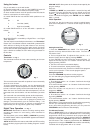
The heater carries the Warning symbol, indicating that
it must not be covered.
Warning: In order to avoid overheating, do not cover the
heater
Caution: In order to avoid a hazard due to inadvertent
resetting of the thermal cutout, this appliance must not be
supplied through an external switching device, such as a
timer, or connected to a circuit that is regularly switched on
and off by the utility.
This appliance is not intended for use by children or other
persons without assistance or supervision if their physical,
sensory or mental capabilities prevent them from using it
safely. Children should be supervised to ensure that they do
not play with the appliance.
If young children, the aged or infirm are likely to be left in the
vicinity of the heater, we advise that adequate precautions
should be taken. We recommend that a guard be fitted to
ensure contact with the heater is avoided and objects cannot
be inserted into the product.
If the mains lead is damaged, it must be replaced by the
manufacturer or its service agent or a similarly qualified
person in order to avoid a hazard.
Electrical connection
WARNING – THIS APPLIANCE MUST BE EARTHED
This heater must be used on an ~ supply only and the voltage
marked on the heater must correspond to the supply voltage.
This heater is fitted with a rewireable plug incorporating a 13
amp fuse. In the event of replacing the fuse in the plug supplied,
a 13 amp fuse approved by ASTA to BS 1362 must be used. If any
other type of plug is used, a 15 amp fuse must be fitted in the
plug, the adaptor, or at the distribution board.
IMPORTANT : If the plug is not suitable for your socket, the 13
amp plug should be removed. Before wiring the appropriate plug,
please note that the wires in this mains lead are coloured in
accordance with the following code :
GREEN AND YELLOW: EARTH
BLUE : NEUTRAL
BROWN : LIVE
Connect the GREEN AND YELLOW wire to the terminal marked
‘E’ or by the earth symbol
, or coloured GREEN or GREEN AND
YELLOW.
Connect the BROWN wire to the terminal marked ‘L’ or coloured
RED.
Connect the BLUE wire to the terminal marked ‘N’ or coloured
BLACK.
Positioning the heater
Always ensure that the heater is stood on a firm, level base near
to, but not directly beneath, a suitable mains supply socket,
ensuring at least 300mm clearance from any shelf above.
Ensure that curtains and furniture are not positioned close to the
chosen position, as this would create a potential fire hazard.
See also ‘Important Safety Advice’.
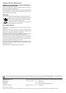
Fitting Feet
NEVER USE THE HEATER FREE STANDING WITHOUT THE FEET
FITTED.
Lay the heater on its back, and locate the foot fixing screw (see ‘a’
in Fig. 2). Remove the screw using an X–head screwdriver, then
align foot over slots and holes in base and slide home. Finally
take the foot fixing screw, insert and tighten using a screwdriver
to secure the foot.
Fig. 2
Fig. 1