


cable or
conduit entry
350mm min.
35mm
510mm
shelf
1
50mm min
8mm
350mm
280mm
Ø10mm
6mm
575mm
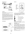
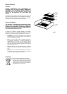
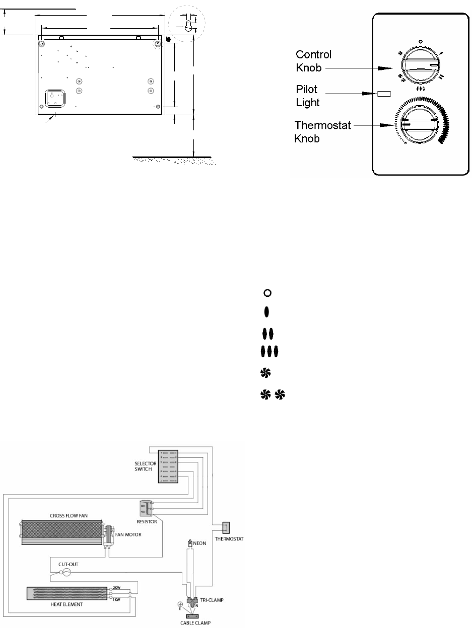
Fixing dimensions
Procedure
Release the front cover from the unit by undoing the two screws
under the bottom edge.
Carefully remove cover by pulling bottom-front forward, and
then lift to release top from retaining slots.
Mark screw fixing positions on wall in accordance with the
dimensions shown on the diagram in Fig 2. The unit must be
secured to the wall with four screws through the holes provided.
The two upper holes are keyhole shaped to enable the two
upper screws to be positioned first. The unit can then be hung
on these screws while the two lower screws are positioned.
Before finally tightening all four screws, ensure the unit is truly
horizontal.
Fit a 3 core 1.5 square millimetre flexible cord through the cable
entry bush, connect wires to the appropriate terminals and
tighten cable clamp. Alternatively the heater may be connected
with conduit through the base after removing the knockout
containing the cable entry bush (see Fig. 2).
Wiring Diagram
Fig. 3
Operation
Fig. 4 - Controls & Control
Panel Layout
The Dimplex WFC 3NB and WFC 3NS have a total loading of
3Kw. They are fitted with two control knobs and a pilot light. The
air inlet is in the front panel, and the outlet on the underside.
The upper knob operates a six-position switch, giving a choice
of operating characteristics as follows :
▬
Off
▬ 1Kw of heat, low fan speed.
▬ 2Kw of heat, medium fan speed.
▬
3Kw of heat, high fan speed.
▬
Fan only, low speed.
▬ Fan only, high speed.
The lower knob operates a thermostat which enables the
temperature of the room to be regulated.
The pilot light indicates when the appliance is connected to the
electricity supply.
Thermal Safety Cut-out
In the event that the appliance overheats, the cut-out switches
the heater off automatically. To bring the heater back into
operation, remove the cause of overheating, then turn Off the
electrical supply to the heater for a few minutes. When the
heater has cooled sufficiently reconnect and switch On the
heater. If the cut-out operates repeatedly, contact your supplier.
To control the room temperature, set the mark on the
thermostat knob to the required temperature on the visually
graduated scale (see Fig. 4). The thermostat will monitor
continuously the temperature of the air returning to the inlet
grille, and the heater element(s) selected will achieve or
maintain the chosen temperature level efficiently and
economically.
When running Fan only modes, rotate thermostat knob to ‘max.’
position to ensure continuous cool air
Fig. 2