


If the unit is to be connected to a Building Energy Management
System, connections are made as per Fig. 7 & 8 as appropriate.
Ensure that the air curtain is securely fastened in position and
that the supply cables are firmly clamped before operating the
appliance.
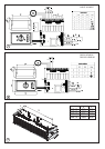
Water connection
Models designed for use in conjunction with a low pressure hot
water supply should be individually connected (in a parallel
circuit) to the flow and return pipe-work. Connections (see ‘a’ in
Fig. 5) are: ½” BSPT (CAB series) and ¾” BSPT (DAB series)
and isolation valves (see ‘b’ in Fig. 5) should be fitted as close
to the air curtain connection points as possible. For
commissioning, air bleed valves (see ‘c’ in Fig. 5) are fitted to
the coil, which can be accessed by removal of the bottom panel
and intake grille assembly - see Fig. 4. The drain (see ‘d’ in Fig.
5) can also be accessed when the intake grille assembly and
bottom panel are removed.
Maximum water supply conditions are 125ºC and 8 bar
(0.8MPa).
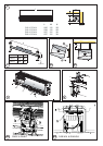
To aid installation, the water coil connections may be moved to
either side of the appliance. By removing the water coil and
appropriate knockouts the water coil can then be re-inserted
into the required orientation. This procedure should be carried
out before mounting the appliance.
Switch Panel Installation
The backing box (standard double gang) should be rebated
into a suitable wall. The box should be fitted so that the switch
panel will be flush with the wall. Suitable conduit should be
used where applicable to carry the cable between the heater
and the switch. A CAT5 LAN cable with straight through
connections should be used to connect the switch panel to the
appliance PCB.
Warning: Ensure cable is secure and the cable path does not
come into contact with heater element or other moving parts.
Test all switch settings once installation is complete.
Electrically heated variants
Operation using switch box - CABC5
Switch on electrical supply to the air curtain. Rotate the switch
to the desired heat setting. Settings available are;
OFF - Low Fan - Low Fan with Low Heat &
High Fan - High Fan with Low Heat - High Fan with Full Heat
The rocker (auto / manual) switch allows for manual over-ride of
a door switch if fitted. Manual allows the appliance to run at the
desire setting, while Auto provides an energy saving feature by
shutting down the appliance while the door is closed.
The unit should always be switched OFF using the switch box
control, and not by mains power supply interruption.
When the unit is switched off (via the switch box) the fan will run
on for 1 minute without heat to discharge any residual energy
from the heating elements.
When first turned on the control will run through a system check.
The selected settings will be reached and maintained after a 30
second period.
Thermostatic control
A capillary type thermostat is factory fitted within the unit, as per
‘C’ in Fig. 7, giving a selection scale of 0-40ºC. When the
thermostat operates, the power output will reduce depending
on the switch setting.
- Fan only - No effect
- Half Heat - Heater will reduce to Fan only
-Full Heat - Heater will reduce to Half Heat
To override the thermostat, first Isolate the supply to the heater.
Remove the connection on terminal ‘1’ of the thermostat and
reconnect it onto the piggy back connection on terminal ‘C’.
Door switch control (Electric models)
By including a door switch in the circuit (as per ‘D’ in Fig. 7) the air
curtain will respond to door openings as follows:
(1) Door opening will energise the air curtain at the set
conditions (switch box settings).
(2) On door closure operation will continue at the set conditions
for a further 1 minute.
(3) Between 1 minute and 2 minutes from door closure, set
back operation, ½ heat (if heat selected) and ½ fan will
activate.
(4) Between 2 minutes and 3 minutes, the fan only (½ speed)
shut down cycle will be engaged.
(5) After 3 minutes, the air curtain will return to a dormant state
until the door is re-opened.
If the door re-opens during this 3 minute run on cycle, the
process will restart at (1).
Thermal Safety cut outs
The power supply to the heating elements will be interrupted if
one or a combination of the following abnormal events occur:
1. Air inlet or outlet grilles are obstructed.
2. Internal ventilation is impaired due to build up of dust
and fluff.
3. Blower unit stalls.
To reset the thermal safety cut-outs, access reset buttons as
shown in Fig. 9. Before re-setting the reason for activation must
be determined and corrective action taken.
Low pressure hot water heated / Ambient (fan
only) variants
Operation using switch box - CABC6
Switch on electrical supply to the air curtain. Rotate the switch to
the desired heat setting. Settings available are;
OFF - Low Fan - High Fan
The rocker (auto / manual) switch allows for manual over-ride of
a door switch if fitted. Manual allows the appliance to run at the
desire setting, while Auto provides an energy saving feature by
shutting down the appliance while the door is closed.
The unit should always be switched OFF using the switch box
control, and not by mains power supply interruption.
When first turned on the control will run through a system check.
The selected settings will be reached and maintained after a 30
second period.
Thermostatic control (optional)
1) A thermostatic regulation valve with a remote sensing bulb
(not supplied) can be positioned in the supply water pipe-work to
regulate the heat output.
2) An electrical 3-Port Solenoid Valve can also be connected into
the system. Please contact your service agent using the contact
details for more details.
Door switch control (Water heated & Ambient models)
By including a door switch in the circuit (as per ‘D’ in Fig. 8) the air
curtain will respond to door openings as follows:
(1) Door opening will energise the air curtain at the set
conditions (switch box settings).
(2) On door closure operation will continue at the set conditions
for a further 1 minute.
(3) Between 1 minute and 2 minutes from door closure ½ fan
set back operation will activate.