


IMPORTANT: THESE INSTRUCTIONS SHOULD BE READ CAREFULLY AND RETAINED FOR FUTURE REFERENCE
IMPORTANT SAFETY ADVICE
DO NOT COVER OR OBSTRUCT the air inlet or outlet grille.
ENSURE THE APPLIANCE IS EARTHED.
Do not use this heater in areas where excessive dust exists.
This heater must not be located immediately above or below
a fixed socket outlet or connection box.
Always disconnect supply before working on the product.
This appliance should only be connected to the fixed wiring
of the premises by means of conduit.
This product should be mounted safely to solid wall or ceiling
surfaces only.
This product must not be subjected to water spray or
immersion.
Ensure the supply cables are of adequate current carrying
capacity and are protected by a suitable fuse.
If the appliance is mounted in a toilet or washroom, the
appliance should be mounted such that no part of it can be
touched by a person using a fixed bath or shower.
If the appliance is mounted in a toilet or washroom an
isolating switch must be provided outside the washroom
adjacent to the entrance door.
This appliance is not intended for use by persons (including
children) with reduced physical, sensory or mental
capabilities, or lack of experience and knowledge, unless
they have been given supervision or instruction concerning
use of appliance by a person responsible for their safety.
WARNING: Isolate electrical supply to ALL modular linked
units when carrying out maintenance.
Models
Electrical
The installation of this appliance should be carried out by a
competent electrician and be in accordance with the current IEE
wiring regulations.
Dimplex Compact Air Curtains
Models : CAB10E, CAB15E, CAB10W, CAB15W, CAB10A, & CAB15A
DAB10E, DAB15E, DAB10W, DAB15W, DAB10A, & DAB15A
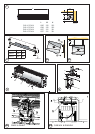
Fixing Positions
This appliance may be either wall-mounted or fixed to a ceiling -
see Fig. 3a & 3b for fixing positions and ‘Mounting’ sections
below for fixing details.
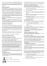
A minimum distance of 100mm is required from the top of the
appliance to ceiling - see ‘a’ in Fig. 1.
The distance between the bottom of the appliance and the top of
a door should be kept to a minimum - see ‘b’ in Fig. 1.
This appliance should not be mounted less than 1.8m from the
floor.
Wall Mounting
Using the wall mounting bracket as a guide (see Fig. 2) mark off
hole positions on the wall (a minimum height of 2.0 metres is
required from the floor level to the bottom of the bracket). Position
the bracket such that the air outlet of the installed air curtain will
be as close to the top of the doorway as possible but will remain
unobstructed when installation is complete.
Solid brick or concrete block walls must be drilled and plugged
(using a spirit level as a guide - see ‘x’ in Fig. 2 - to ensure the
bracket is level) with rawlplug No. 8 size fibre inserts. The plug
must be located in the solid part of the wall and not just in the
plaster layer.
When fixing to ‘panel’ walls, the wall bracket should be attached
to the stud-work using No. 8 wood screws or by an alternative,
equally secure method of fixing.
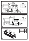
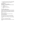
Once the wall bracket has been fitted, the air curtain can be
clipped in place as shown in Fig. 3a.
Ceiling Mounting
By using threaded inserts in the top panel of the air curtain,
attachment to a ceiling over the product can be achieved using
suitable M8 threaded steel rod or similar supports of sufficient
strength - see Fig. 3b.
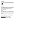
Electrical connection
All products are fitted with a microprocessor control. Electrical
power and control connections are made as shown in Fig. 6. A
suitable local isolating switch must be provided in the electrical
supply circuit with at least 3mm clearance on each pole.
In order to access the electrical connections, remove the outlet
grilles (‘x’ and ‘y’ in Fig. 4) by releasing the quick release fasteners
and hinging the mouldings as shown and then remove the
bottom panel (‘z’ in Fig. 4).
For the Water heated and Ambient models only, the pressure
plate (‘w’ in Fig. 4) must also be removed.
All Electric Models - Having removed a ‘knock out’ in the top
panel, feed an appropriate supply cable (see ‘a’ in Fig. 6A) through
a suitable cable gland (not supplied) fitted in the top panel and
attach to the terminal block (see ‘b’ in Fig. 6A).
All Water heated and Ambient Models - Having removed
a ‘knock out’ in the top panel, feed an appropriate supply cable
(see ‘a’ in Fig. 6B) through a suitable cable gland (not supplied)
fitted in the top panel and attach to the PCB (see ‘b’ in Fig. 6B).
All Models - A suitable cable (CAT5 or equivalent) for a switch
panel (kit ref. - CABC5 for electrically heated models or CABC6
for water heated/ambient models) can be similarly introduced
through the top panel and plugged into the circuit board as shown
in Fig. 6A & 6B. If the unit is to be operated in conjunction with a
door switch, a normally open switch should be wired as per Fig.
7 & 8 as appropriate.
Note: If using a door switch, an additional 2 core (low Voltage)
cable is required between the door switch and the air barriers.
AMBIENT / COLD STORE
CAB10A n/a 220-240V ~1PN 0.3 15.5 3.0
CAB15A
n/a 220-240V ~1PN 0.5 21.5 3.0
DAB10A
n/a 220-240V ~1PN 1.5 21.5 4.0
DAB15A
n/a 220-240V ~1PN 2.3 27.5 4.0
ELECTRICALLY HEATED
CAB10E 4.5 / 9.0 380-415V ~3PN 14 20.5 3.0
CAB15E 6.75 / 13.5 380-415V ~3PN 20 29 3.0
DAB10E 6.0 / 12.0 380-415V ~3PN 18 26.5 4.0
DAB15E 9.0 / 18.0 380-415V ~3PN 27 35 4.0
WATER HEATED (at 82/71 °C - LPHW)**
CAB10W 9.0 220-240V ~1PN 0.3 17.7 3.0
CAB15W 13.5 220-240V ~1PN 0.5 24.6 3.0
DAB10W 12.0 220-240V ~1PN 1.5 24.7 4.0
DAB15W 18.0 220-240V ~1PN 2.3 31.9 4.0
Max
Installed
height
m
Model
Heat
output
kW
Electrical
load
(per phase)
Weight
kg
Electrical
Supply