


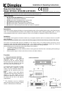
2. Power supply connection
Check that the supply voltage details on the heater are in accordance with your electricity supply. A 2.5 metre length of
inter-connecting cable is supplied. The 6 core inter-connecting cable should be routed from the plinth space to the
connection box, ensuring that the cable is left with enough slack to allow removal of the appliance for maintenance. The
cable must be protected from any sharp edges.
a.) Remote Control Switch Panel
Determine desired position for remote control switch
panel above work bench i.e. 900mm minimum above
floor level. It is designed for use with either a surface
mounted or flush mounted box as listed in the Table
opposite. The left hand column of the Table indicates
the type of conduit/trunking required, if any, and the right
hand column indicates the corresponding two gang box
for the control switch panel. Fix the chosen mounting
box in position.
b.) Electrical Connection to Remote Control Panel
Strip back the outer sheath of the inter-connecting cable
by 125mm, at both ends. The conductor sheath should
be stripped back by 8mm. Select suitable trunking or
conduit from the Table if required. Connect remote
control switch panel to the six core inter-connecting
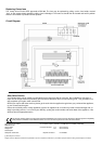
cable, in accordance with the wiring diagram.
If the 2.5 metre length of cable supplied is insufficient and a substitute cable is used, Ensure that the conductors are of
minimum 1.5mm² cross-sectional area. The same size of conductor should be used to link the switch and fuse terminals
on the remote control switch panel as indicated in the wiring diagram.
c.) Electrical Connection to Appliance
Remove the screws securing the top, front and rear covers in order to gain access to the terminal block. Feed the 6
core flexible inter-connecting cable through the cable-clamp at the side of the heater and connect it to the terminal block
in accordance with the wiring diagram. It may be necessary to remove the terminal block from its fixing while making
connections to it.
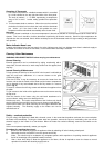
3. Fitting the Rear Support Bracket
The heater is supplied with a rear support bracket. Fit to the back of the appliance with the two screws supplied. Adjust
the rear support bracket so that the vertical distance from the underside of the appliance to bottom of the rear support
bracket equals the vertical distance from the floor in the cupboard space to the bottom of the aperture opening. The
slots in the rear support bracket allow it to be adjusted to the required height.
4. Marking the Fixing Positions
Slide the heater into position in the plinth aperture. Mark the six fixing holes (two on each side and two on the top
Remove the heater and drill 2mm pilot holes.
5. Mounting the Heater into the Plinth
When the cable connection has been made and the rear support bracket adjusted, slide the heater into the aperture
ensuring that it is adequately supported and that the inlet grille is not obstructed. Use the six screws provided to secure
the heater to the plinth. (See point 6 below for stainless steel grill fitting).
6. Stainless Steel Grille (BFH24RS model only).
The stainless steel grille is supplied (in the plastic covering) as an attachment for the front of the heater.
This should be offered up to the front of the heater before fixing the heater to the plinth. Use the six screws to secure it
to the front of the heater / plinth.
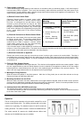
Flush or Surface
Mounting
Conduit/Trunking
Two Gang box for
Remote Control Switch
MK Switches
1. Embedded – Rounded
or oval conduit
2. Surface Mounting mini-
trunking
3. Surface Mounting –
Cable clipped to wall
4. DryLining Box
1. MK 892 ALM (Metal)
2. Marshall Tufflex MSSB
16 (PVC White)
3. MK 2142 WHI (White
Moulded)
4. Marshall Tufflex MDLB
2 (Plastic)
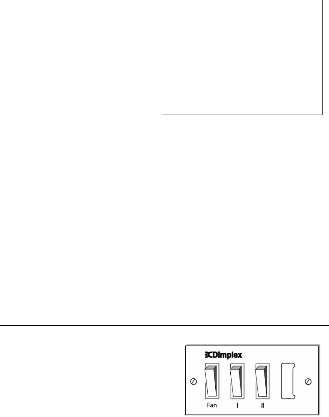
Operation
The fan is brought into operation using the switch marked Fan on the
remote control switch panel. The heating elements will not function
until the fan is operating. The switches marked ‘I‘ and ‘II’ control the
heating elements. The switch marked ‘I’ controls the 800W element.
The switch marked ‘II’ controls the 1600W element. When both
switches are ON 2400W heat output is available.