


24
www.desatech.com
116234-01B
OPERATING FIREPLACE
To Turn Off Gas To Appliance
Optional Remote Operation
Operating Optional Blower Accessory
INSPECTING BURNERS
Pilot Assembly
Burner Flame Pattern
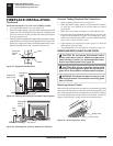
TO TURN OFF GAS
TO APPLIANCE
1. Turn off the wall switch.
2. Turn off all electric power to the appliance if service is to
be performed.
3. Open lower louver panel.
4. Remove front hearth brick and control access panel.
5. Turn equipment shutoff valve clockwise
to OFF.
Do not force.
6. Close lower louver panel.
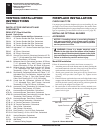
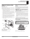
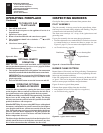
Figure 43 - Pilot
Sensing Rod
Pilot Burner
Ignitor
OPTIONAL REMOTE
OPERATION
Note: The WRC receiver and hand-held remote control kit
must be purchased separately (see Accessories, page 34). Follow
installation instructions on page 22.
1. Turn equipment shutoff valve to ON position. You can now turn
the burner on and off with the hand-held remote control unit.
IMPORTANT: Be sure to press the ON/OFF buttons on the
hand-held remote control unit for up to 3 seconds to assure
proper operation.
2. Press the ON/OFF button to turn the burner on and off.
OPERATING OPTIONAL
BLOWER ACCESSORY
Locate the blower controls by opening the lower louver panel
on the fireplace. Blower controls are located on the left side of
the switch bracket to the right just inside the louver panel.
The BK manual blower and the BKT thermostatically-controlled
blower have an ON setting and an OFF setting. The blower
will only run when the switch is in the ON position. In the OFF
position, the blower will not operate.
Note for BKT Only: If you are using BKT blower with optional
thermostat (wall mounted or remote control) for the fireplace,
your fireplace and blower will not turn on and off at the same
time. The fireplace may run for several minutes before the blower
turns on. After the heater modulates to the pilot position, the
blower will continue to run. The blower will shut off after the
firebox temperature decreases.
The blower helps distribute heated air from the fireplace. Peri-
odically check the louvers of the firebox and remove any dust,
dirt or other obstructions that will hinder the flow of air.
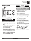
BURNER FLAME PATTERN
Burner flames will be steady; not lifting or floating. Flame patterns
will be different from unit to unit and will vary depending on instal
-
lation type and weather conditions.
If the vent configuration is installed incorrectly, the flames will lift
or "ghost". This can be dangerous. Inspect the flames after instal-
lation to ensure proper installation and performance.
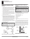
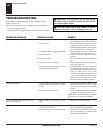
Figure 45 shows a typical flame pattern.
If burner flame pattern differs from that described:
• turn fireplace off (see To Turn Off Gas to Appliance)
• see Troubleshooting
, page 26
Figure 45 - Typical Flame Pattern
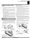
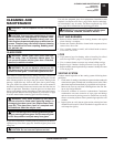
Pilot Burner
Ignitor/Sensor
INSPECTING BURNERS
Check pilot flame pattern and burner flame patterns often.
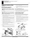
PILOT ASSEMBLY
The pilot assembly is factory preset for the proper flame. Altera-
tions may have occurred during shipping and handling. The pilot
is located on the left hand side of the burner.
The flame must envelope 1/4" of top of the ignitor/sensor and
grounding stem.
If your pilot assembly does not meet these requirements:
• Turn the adjustment screw marked PILOT clockwise to decrease
or counterclockwise to increase the flame to proper size (see
Figure 42, page 23). Do not remove the adjustment screw.
• see Troubleshooting, page 26
Figure 44 - Correct Pilot Flame Pattern
Sensing Rod
OPERATING FIREPLACE
Continued