


108860-01C
For more information, visit www.desatech.com
For more information, visit www.desatech.com
10
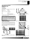
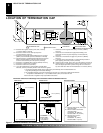
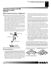
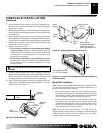
GROUND FLOOR INSTALLATION
Recommended Applications:
• Installation using cabinet surrounds
• Through the wall using round or square termination (up to 12"
horizontal pipe)
• NOT FOR CORNER INSTALLATION
VENTING INSTALLATION
INSTRUCTIONS
Continued
VENTING INSTALLATION INSTRUCTIONS
Installation Planning (Cont.)
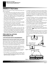
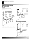
Horizontal Termination Configurations
Figures 14 through 18 show different configurations and alternatives
for venting with horizontal termination. Each figure includes a chart
with critical minimum and maximum dimensions which MUST be
met.
IMPORTANT:
Remember that a horizontal run of venting must
have a 1/4" rise for every 12" of run toward the termination.
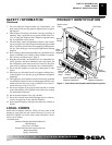
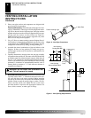
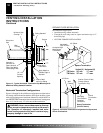
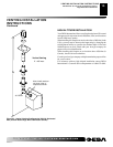
Figure 13 - Typical Horizontal Termination Cap Mounting with
Additional Siding Standoff Installed
Siding Standoff
Screws
High Wind
Termination
Apply Mastic to
Outside Edge of
Standoff
Exterior Wall
with Vinyl Siding
10" x 10"
Framed
Opening
Maintain 1"
Minimum Air
Space Around
Outer Pipe When
Penetrating a Wall
Minimum Pipe
Overlap 1
1
/4"
Wall
Firestop
Direct Vent
Pipe
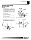
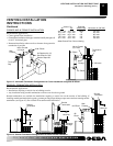
WARNING: Never run vent downward as this may
cause excessive temperatures which could cause a
fire. Operation of improperly installed and main-
tained venting system could result in serious injury,
property damage or loss of life.
Horizontal High
Wind Square
Termination
Wall Firestop
45° Elbow
Adjustable
Pipe 12" Max.
Vertical (V) Horizontal (H)
T32 Series 29" min. 17" max.
T36 Series 32" min. 17" max.
Square Termination
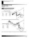
Figure 14 - Horizontal Termination Configuration for Square and
Round Terminations
45° Elbow
Wall
Firestop
Round
Termination
Cap
Exterior Portion of Wall
Firestop (Round
Termination Only)
Round Termination
(Kit HTK Shown)
Slide Ring
Over Elbow to
Complete
Connection