


www.desatech.com 113132-01A
10
INSTALLATION
Continued
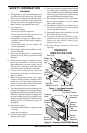
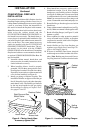
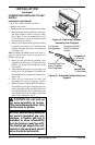
4. Place hearth base accessory against wall at
installation location. Cut an access hole in
hearth top to run flexible gas line to fireplace
(see Figure 9). Make sure to locate access hole
so cabinet mantel will cover it when installed.
Note:
You can secure base to floor using wood
screws. Countersink screw heads and putty over.
5. Route flexible gas line through access hole in
hearth base.
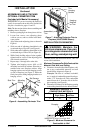
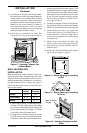
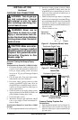
6. Center cabinet mantel on hearth base (see Fig-
ure 10). Make sure mantel is flush against wall.
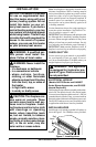
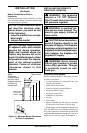
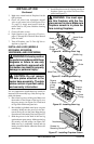
7. Break off nailing flanges (see Figure 11) with
hammer or pliers.
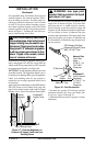
8. Place cardboard or other protective material
on top of hearth base. Carefully set fireplace
on protective material, with back of fireplace
inside mantel opening.
9. Attach flexible gas line from fireplace gas
regulator to gas supply. See Connecting Fire-
place to Gas Supply, page 14.
10. If blower is installed, route blower electrical
cord through access holes in either side of fire-
place.
Note:
Bushing may be moved if neces-
sary. Plug electrical cord into electrical outlet.
CONVENTIONAL FIREPLACE
INSTALLATION
Conventional installation of this fireplace involves
installing fireplace along with the corner, face, or
cabinet mantel with hearth base accessories against
a wall in your home. Follow the instructions in
this section to install the fireplace in this manner.
Note:
The instructions in this section show instal-
lation using the cabinet mantel and the
G3333F/G3334U/G3004W/G3335F/G3007U se-
ries hearth base accessories. The hearth base ac-
cessory shown is optional for this installation. You
can install fireplace and cabinet/corner mantel di-
rectly on the floor. The corner mantel accessory
cannot be installed with the G3333F/G3334U/
G3004W/G3335F/G3007U hearth base. The cor-
ner mantel can be paired with the G3008F/
G3009U/G3010F corner hearth base. If mounting
fireplace and cabinet or corner mantel to the floor,
an optional G3005J/3005S/3005B Slim Base kit
may be installed.
1. Assemble cabinet mantel, hearth base, and
trim accessories. Assembly instructions are in-
cluded with each accessory.
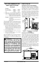
2. When installing blower, install a properly
grounded, 120 volt three-prong electrical out-
let at fireplace location if an outlet is not there.
If possible, locate outlet so cabinet mantel will
cover it when installed (see Figure 9).
3. Install gas piping to fireplace location. This
installation includes an approved flexible gas
line (if allowed by local codes) after the equip-
ment shutoff valve. The flexible gas line must
be the last item installed on the gas piping.
See Installing Gas Piping to Fireplace Loca-
tion, pages 12 and 13.
Figure 10 - Installing Cabinet Mantel
Cabinet
Mantel
Figure 9 - Placing Hearth Base
Accessory Against Wall
Electrical Outlet
Hearth Base
Rigid Pipe and Gas
Shutoff Valve
Gas Line
Access Hole
Figure 11 - Location of Nailing Flanges
Nailing
Flanges