


www.desatech.com
107172-01K10
*
INSTALLATION
Continued
INSTALLATION CLEARANCES
WARNING: Maintain the
minimum clearances. If you
can, provide greater clearances
from floor, ceiling and adjoining
wall.
Carefully follow the instructions below. This will
ensure safe installation.
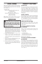
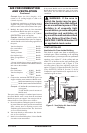
Minimum Clearances For Side
Combustible Material, Side Wall and
Ceiling
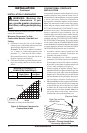
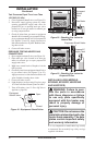
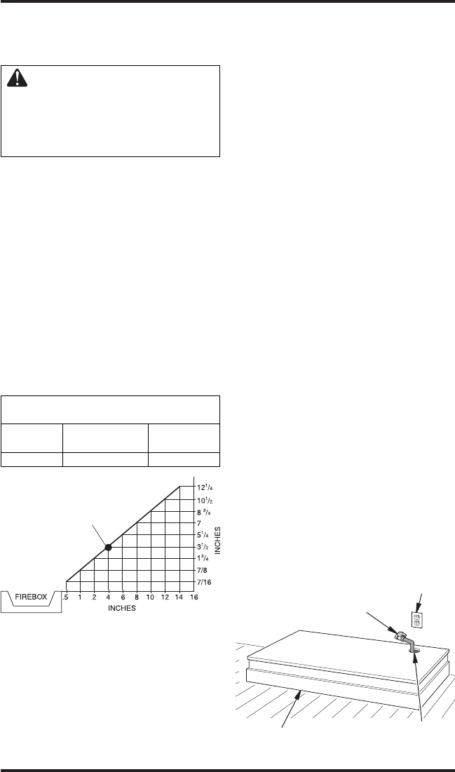
A. Clearances from the side of the fireplace
cabinet to any combustible material and wall
should follow diagram in Figure 8.
Example: The face of a mantel, bookshelf,
etc. is made of combustible material and
protrudes 3
1
/
2
" from the wall. This combus-
tible material must be 4" from the side of the
fireplace opening (see Figure 8).
B. Clearances from the top of the fireplace open
-
ing to the ceiling should not be less than 42
inches.
*Minimum 16 inches from Side Wall
Example
Figure 8 - Minimum Clearance for
Combustible to Wall
CONVENTIONAL FIREPLACE
INSTALLATION
Conventional installation of this fireplace involves
installing fireplace along with the corner, face or
cabinet mantel with hearth base accessories against
a wall in your home. Follow the instructions in
this section to install the fireplace in this manner.
Note: The instructions in this section show instal
-
lation using the cabinet mantel and the GC3333F/
GC3334U/G3004W/GC3335F/G3007U series
hearth base accessories. The hearth base accessory
shown is optional for this installation. You can
install fireplace and cabinet/corner mantel directly
on the floor. The corner mantel accessory cannot be
installed with the GC3333F/GC3334U/G3004W/
GC3335F/G3007U hearth base. The corner mantel
can be paired with the G3008F/G3009U/G3010F
corner hearth base. If mounting fireplace and cabinet
or corner mantel to the floor, an optional G3005J/
3005S/3005B Slim Base kit may be installed.
1. Assemble cabinet mantel, hearth base and
trim accessories. Assembly instructions are
included with each accessory.
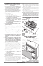
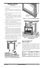
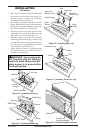
2. When installing blower, install a properly
grounded, 120 volt three-prong electrical out
-
let at fireplace location if an outlet is not there.
If possible, locate outlet so cabinet mantel will
cover it when installed (see Figure 9).
3.
Install gas piping to fireplace location. This in-
stallation includes an approved flexible gas line
(if allowed by local codes) after the equipment
shutoff valve. The flexible gas line must be the
last item installed on the gas piping. See Install
-
ing Gas Piping to Fireplace Location, page 13.
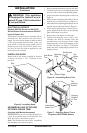
4. Place hearth base accessory against wall at instal-
lation location. Cut an access hole in hearth top
to run flexible gas line to fireplace (see Figure
9). Make sure to locate access hole so cabinet
mantel will cover it when installed. Note: You
can secure base to floor using wood screws.
Countersink screw heads and putty over.
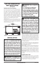
MINIMUM CLEARANCE TO
COMBUSTIBLE MATERIALS
Top Left and Bottom
Right Sides and Rear
0" 16" 0"
*
Figure 9 - Placing Hearth Base
Accessory Against Wall
Electrical Outlet
Hearth Base
Rigid Pipe and Gas
Shutoff Valve
Gas Line Access Hole