


110720-01C
7
7
For more information, visit www.desatech.com
For more information, visit www.desatech.com
INSTALLATION
Thermostat Sensing Bulb (Thermostat Models Only)
Installing Heater To Wall
INSTALLATION
Continued
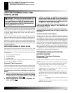
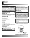
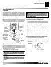
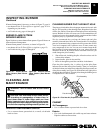
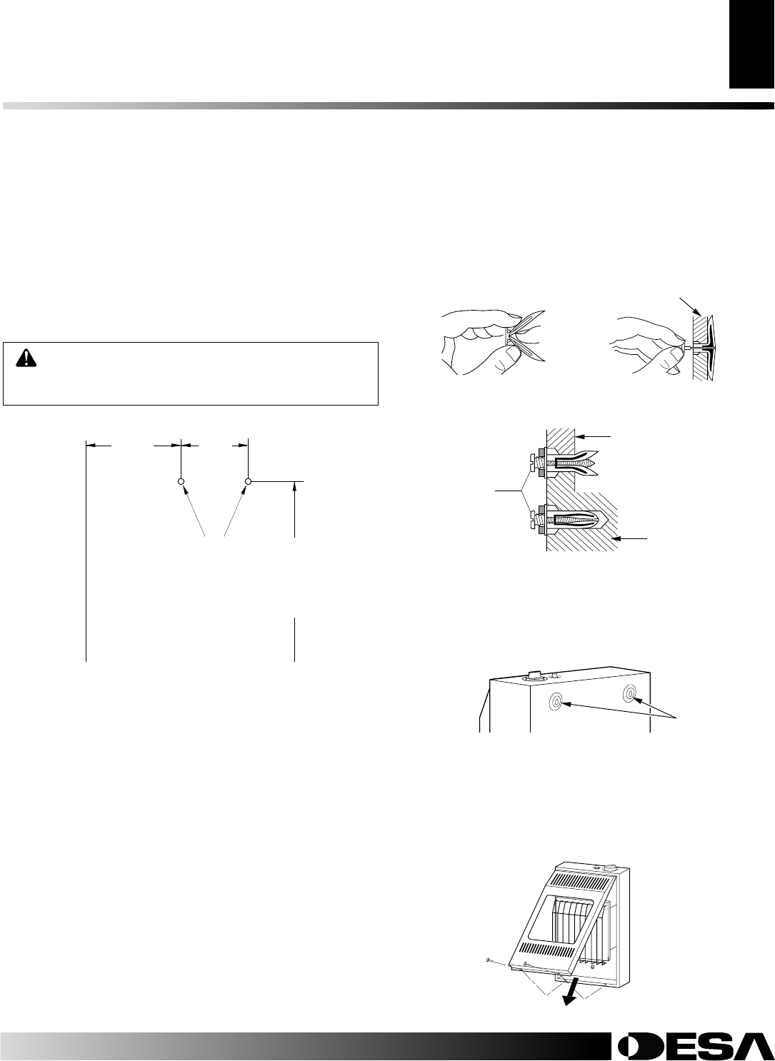
Figure 5 - Mounting Screw Locations
INSTALLING HEATER TO WALL
Marking Screw Locations
1. Determine where you will locate heater.
WARNING: Maintain minimum clearances shown
in Figure 5. If you can, provide greater clearances
from floor and joining wall.
2. Mark two mounting screw locations on wall (see Figure 5).
Installing Two Mounting Screws
Note:
Wall anchors and mounting screws are in hardware package.
The hardware package is provided with heater.
Attaching to wall stud method
For attaching mounting screw to wall stud
1. Drill hole at marked location using 9/64" drill bit.
2. Insert mounting screw into wall stud.
3. Tighten screw until 1/16" space (thickness of penny) is be-
tween screwhead and wall.
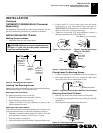
Attaching to wall anchor method
Follow instructions below to attach mounting screws to hollow walls
(wall areas between studs) or solid walls (concrete or masonry).
1. Drill holes at marked locations using 5/16" drill bit. For solid
walls (concrete or masonry), drill at least 1
1
/4" deep.
2. Fold wall anchor (see Figure 6).
3. Insert wall anchor (wings first) into hole. Tap anchor flush to wall.
Mounting
Screw
Locations
8
7
/8"
Blue Flame
10
7
/8" Plaque
Minimum To
Maintain 6"
Clearance
From Wall
7
3
/4"
20
1
/4"
Minimum To
Maintain 3"
Clearance
From Floor
FLOOR
JOINING WALL
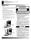
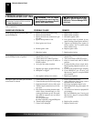
Figure 6 - Folding Anchor
Thin Walls (1/4" to 1/2" thick)
Figure 7 - Popping Open Anchor
Wings For Thin Walls
Figure 8 - Tightening Anchors
Thin or
Thick Wall
(thick wall
shown)
Solid
Wall
1/16"
Space
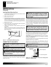
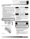
Placing Heater On Mounting Screws
1. Locate two keyhole slots on back panel of heater (see Figure 9).
2. Place large openings of slots over screwheads. Slide heater
down until screws are in small portion of slots.
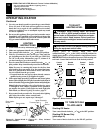
Removing Front Panel Of Heater
1. Remove two screws near bottom corners of front panel.
2. Lift straight up on grill guard until it stops. Grill guard will slide
up about 1/4".
3. Pull bottom of front panel forward, then down.
Figure 10 - Removing Front Panel Of Heater
Figure 9 - Location Of Keyhole Slots On Back Panel Of Heater
Keyhole Slots
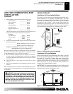
THERMOSTAT SENSING BULB (Thermostat
Models Only)
The thermostat sensing bulb is located inside the heater. Do not
move this bulb during installation or operation of the heater.
4. For thin walls (1/2" or less), insert red key into wall anchor.
Push red key to “pop” open anchor wings (see Figure 7).
IMPORTANT:
Do not hammer key! For thick walls (over 1/2"
thick) or solid walls, do not pop open wings.
5. Tighten two screws until 1/16" space (thickness of penny) is
between screwheads and wall (see Figure 8).