


110749-01B
For more information, visit www.desatech.com
For more information, visit www.desatech.com
9
9
BUILT-IN FIREBOX INSTALLATION
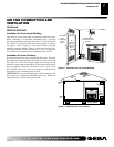
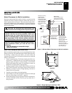
Built-in installation of this firebox involves installing firebox into a
framed-in enclosure. This makes the front of firebox flush with wall.
If installing a mantel above the firebox, you must follow the
clearances shown in Figure 5. Follow these instructions to install the
firebox in this manner.
1. Frame in rough opening. The firebox framing should be con-
structed of 2 x 4 lumber or heavier. Use dimensions and rough
opening layout in Figure 6a. Adjust framing so that firebox
flushes with finished wall surface. If installing in a corner, use
dimensions in Figures 6b for rough opening.
2. Install gas piping to firebox location. See Installing Gas Line on
page 11 and Connecting to Gas Supply in log set owner’s manual.
3. Carefully set firebox in front of rough opening with back of
firebox inside wall opening.
4. Carefully insert firebox into rough opening.
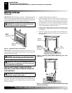
5. Attach firebox to wall studs using nails or wood screws through
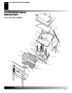
holes in nailing flange (see Figure 7, page 10).
6. Install and properly test gas log heater. Follow installation in-
structions included with the vent-free gas log heater that is
being installed.
INSTALLATION
Continued
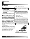
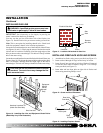
NOTICE: If your installation does not meet the mini-
mum clearances shown, you must do one of the
following:
• raise the mantel to an acceptable height
• remove the mantel
NOTICE: Surface temperatures of adjacent walls and
mantels become hot during operation. Walls and
mantels above the firebox may become hot to the
touch. If installed properly, these temperatures meet
the requirement of the national product standard.
Follow all minimum clearances shown in this manual.
INSTALLATION
Installation Clearances (Cont.)
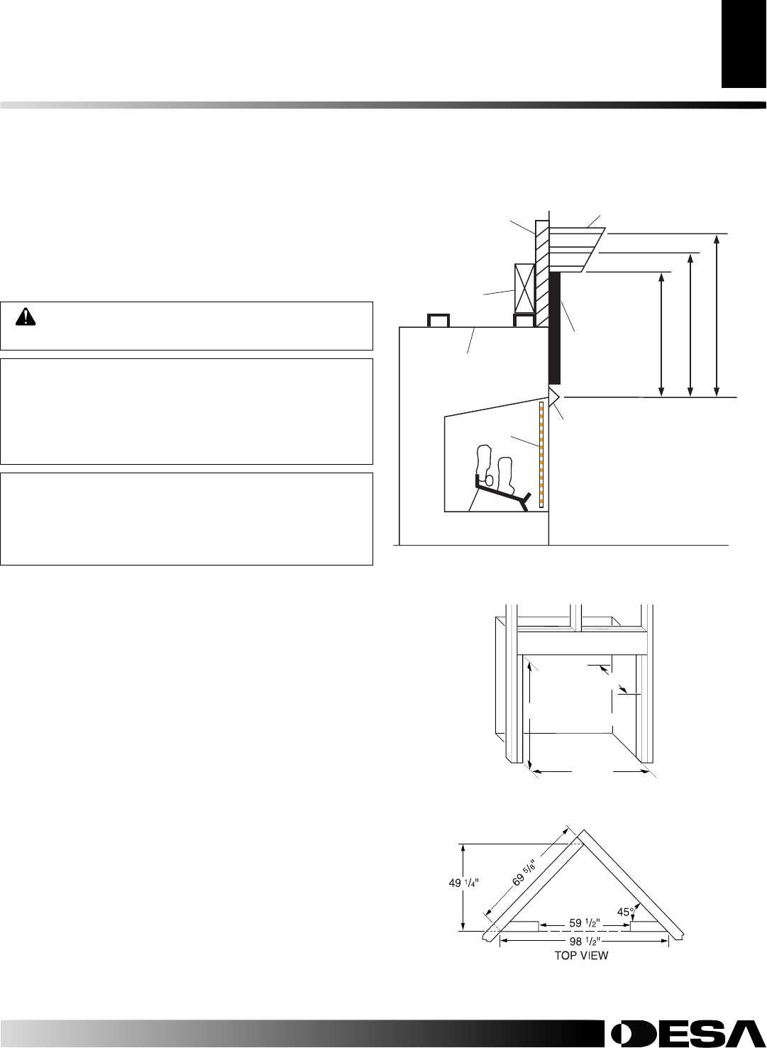
Built-In Firebox Installation
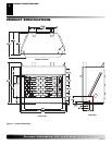
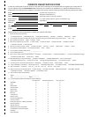
Figure 5 - Minimum Mantel Clearances for Built-In Installation
Supplied Firebox
Hood Must Be
Used at All Times
Wire-mesh
Screen
Firebox
Noncombustible
Material May
Project Off this
Surface above
the Firebox Hood
Mantel Shelf
Note: Any portion of the
mantel shelf must NOT
extend beyond this profile.
12" 16" 20"
1
1
/
2
"
6
3
/
4
"
12"
Note: All vertical
measurements are
from top of fireplace
hood opening to
bottom of mantel shelf.
These minimum
clearances replace any
other recommended
clearances supplied with
your ANSI Z21.11.2
approved gas logs.
Wall board or facing
material (above
firebox) may be of
combustible material,
including decorative
mantel ornaments or
other similar projec-
tions off of the facing
material.
Framing
Material
Figure 6 - Rough Opening for Installing in Wall
30"
59
1
/
2
"
(Inside to Inside)
55"
Mantel Clearances for Built-In Installation
If placing custom mantel above built-in firebox, you must meet the
minimum allowable clearance between mantel shelf and top of
firebox opening shown in Figure 5. These are the minimum allow-
able mantel clearances for a safe installation. Use larger clearances
wherever possible to minimize the heating of objects and materials
placed on the mantel.
CAUTION: Do not allow the vent-free gas log
heater to touch or extend beyond the fireplace screen.
Figure 6b
Figure 6a