


www.desatech.com
56131-F26
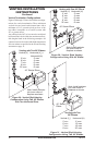
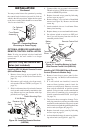
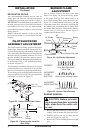
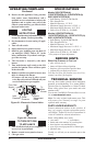
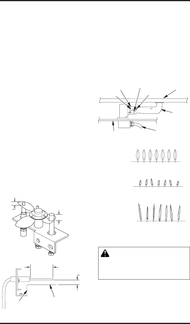
Figure 52 - Correct Pilot Flame Pattern
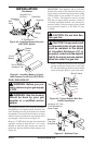
1/8"
(0.3cm)
3/8" - 1/2"
(.95cm-1.3cm)
1/2"
(12.7 mm)
3/4"
(19 mm)
Edge of Burner
Top of
Burner
Figure 53 - Correct Ignitor Location
(Side View)
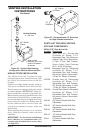
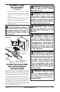
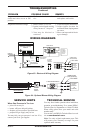
bURNER FLAME
ADjUSTMENT
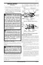
The air shutter, located at the base of the main
burner (see Figure 54), has been factory preset
to the proper air-to-gas ratio which results in an
even, clean burning ame across the burner (see
Figure 55). If readjustment is necessary, you can
restore the proper air-to-gas ratio by loosening the
air shutter screw and rotating the air shutter until
the proper ame setting is achieved (the shutter's
normal setting is fully open. Do not forget to
retighten the air shutter screw.
Figure 55 - Burner Flame Patterns
Figure 54 - Air Shutter Adjustment
Air Shutter
Air
Opening
Burner
Venturi
Tube
Burner Gas Line
CORRECT
INCORRECT
CLOSE
SHUTTER
INCORRECT
OPEN SHUTTER
Short, Sharp, Blowing Flame
Long, Blue Flame with
Yellow Tips
Long, Uneven, Yellow Flame
Firebox Bottom
Adjustment
Screw
Orice
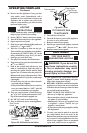
-
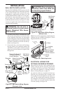
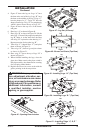
1. Remove top and bottom louvers and screen as-
sembly. Undo 4 latches and open glass door.
2. Carefully remove the log set intact and set
aside (see Figure 56, page 27).
3. Remove the 2 screws holding burner to hearth
pan.
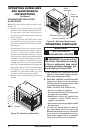
DECORATIVE FACING
Any noncombustible material may be used for
facing (glass, tile, brick, etc.) as long as the proper
clearances are observed (see Clearances, page 6).
IMPORTANT: Louvered openings must not be ob-
structed, and upper and lower panels must remain
removable for servicing. Use only heat-resistant,
noncombustible mortar or adhesive when securing
facing material.
Note: Combustible material, such as wood, that
has been reproofed is not considered noncom-
bustible.
PILOT/ELECTRODE
ASSEMbLy ADjUSTMENT
The pilot assembly is factory preset for the proper
ame height. Alteration to these settings may have
occurred during shipping and handling. If this is the
case, some minor adjustment may be necessary and
should be done by a qualied technician. To access
the pilot assembly, the glass door must be opened.
The proper settings for the thermopile height should
be at a distance of 3/8" to 1/2" from the pilot ame
as shown in Figure 52.
The electrode is installed at the factory for proper
positioning. However, alterations to the position
may have occurred due to shipping and handling.
These settings may need adjustment and must be
done by a qualied technician. The correct position
and height is as shown in Figure 53.
INSTALLATION
Continued