


www.desatech.com
56131-F24
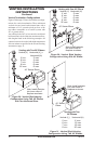
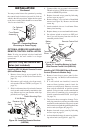
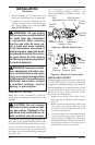
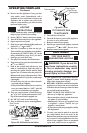
2. Prepare incoming gas line and check with
local codes regarding the use of teon tape.
Complete your gas line installation by con-
necting incoming gas line with exible gas
line. Secure tightly with a wrench, but DO
NOT OVERTIGHTEN.
for leaks after the installation
-
-
-
-
vice, or maintenance can cause
additional information, consult
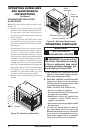
INSTALLATION
Continued
GAS SUPPLY TESTING
Note: This section is intended as a guide for
qualied service technicians installing gas to the
appliance.
CAUTION: Do not connect
-
-
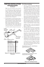
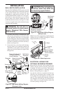
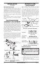
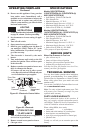
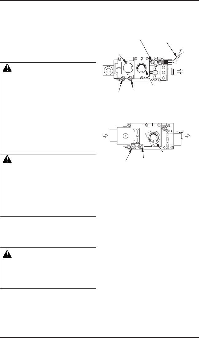
The millivolt system with a manual HI/LO ap-
plies only to the (V)DVF36TPNA/TSDTA and
(V)DVF36TNPA/TSTPA models. The gas control
valve is accessible from the lower control com-
partment. Two pressure taps are provided on the
gas control valve for a pressure gauge connection
(see Figure 44).
O
F
F
P
I
L
O
T
O
N
L
O
H
I
P
I
L
O
T
E A
16AI
7
TPTH TP TH
Figure 44 - Millivolt Control Valve
Pilot
Adjustment Cap
ON/OFF
Knob
Outlet
Pressure
Inlet
Pressure
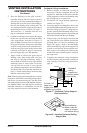
Pilot Gas Line
Do Not Kink
To Pilot
Burner
To Main
Burner
Flame
Adjustment
Knob
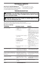
E
A
O
L
H
I
L
P
I
O
T
To Main
Burner
Outlet
Pressure
Inlet
Pressure
Flame
Adjustment
Knob
From
Gas
Supply
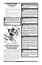
Figure 45 - Electronic Control Valve
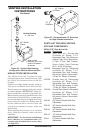
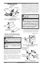
INSTALLING LOG SET
Before proceeding, make sure the gas control valve
is in the “OFF” position. Logs have been shrink
wrapped on a cardboard backing to prevent break-
age during shipping. Cut around perimeter of each
log and pull gently on shrink-wrap to expose log.
Do not pull on log to release it from the shrink-
wrap as this may damage logs.
1. Remove lower louver access panel in re-
place (see step 1 of Wall Switch Installation,
page 21).
2. Remove screen rod by sliding it either to the
left or right of the replace until one of the
rod ends is free and completely remove the
screen from the replace.
3. To open the glass door, undo latches located
on the top and bottom of the rebox (see
Figure 46, page 25). Note: Use caution when
opening these latches. Carefully open the door
by swinging it to the left. The glass door is
mounted to the rebox with 5 screws.
T he e le ct r on ic s ys t em a pp li es t o
t he ( V )D V F3 6 T PN E A/ T ST E A a n d
(V)DVF36TPNPEA/TSTPEA models (see
Figure 45).