


107304-01D
For more information, visit www.desatech.com
For more information, visit www.desatech.com
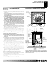
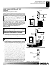
5
5
6
"
4
"
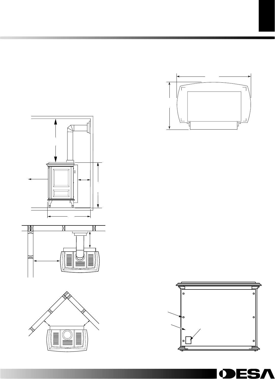
Front
4"
36"
from
Front
42"
Ceiling
Floor
from
Back
Wall
29"
4"
4"
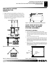
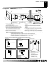
Figure 3 - Clearances for Standard Installation
Figure 4 - Clearance for Corner Installation
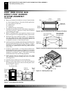
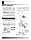
Figure 5 - Stove With Burner System Bottom Dimensions
26
1
/4"
19
1
/2"
Front
3. Proper clearances must be maintained, see Figures 3 and 4.
4. This stove is a freestanding unit designed to set directly on the
floor. If your stove is to be installed directly on carpeting, vi-
nyl tile, or any combustible material other than wood, it must
be installed on a metal or wood panel extending the full width
and depth of the stove. See Figure 5.
PRE-INSTALLATION
PREPARATION
Continued
STOVE BODY ASSEMBLY
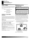
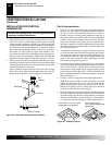
1. Lift off corrugated box enclosing stove body crating.
2. Remove all screws fastening the wood frame enclosure. Spread
wood frame open and lift away from plastic-bagged stove body.
The bottom pieces of pallet wood will remain bolted to the
stove body.
3. Remove plastic bag from stove body.
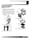
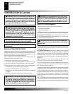
4. Locate the product identification label on the back panel (see
Figure 6) and record the model number and 7 digit serial num-
ber in the space provided in the back of this owner’s manual.
Retain this operation and installation manual for future refer-
ence and warranty.
5. Remove the six (6) bolts on the back stove panel with an ad-
justable wrench or a 10 mm socket. Discard the back panel
and retain the bolts and washers to attach the rear cover pro-
vided with the burner system.
Figure 6 - Removing Back Panel
Bolt
Product
Identification
Label
Back Stove
Panel
CAST IRON STOVE AND
DIRECT-VENT BURNER
SYSTEM ASSEMBLY
PRE-INSTALLATION PREPARATION
Location and Space Requirements (Cont.)
CAST IRON STOVE AND DIRECT-VENT BURNER SYSTEM ASSEMBLY
Stove Body Assembly
27"