


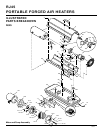

11
104950
OWNER’S MANUAL
Sandpaper
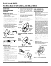
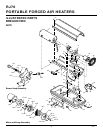
Figure 22 - Sanding Rotor
Figure 21 - Gap Adjusting Screw Locations
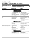
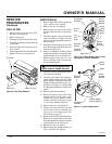
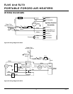
Figure 20 - Rotor Location
O
TOR
PFA/P 056
Insert
Rotor
Air Output
Filter
Blade
Pump Plate
Air Intake Filter
Filter End
Cover
Fan Guard
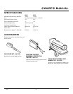
0.08/0.10 mm
Gap Measured
With Feeler
Gauge
Blade
Rotor
Gap Adjusting Screw
Gap Adjusting Screw
SERVICE
PROCEDURES
Continued
NOZZLE (RJ70)
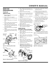
1. Remove upper shell (see Upper Shell
Removal, page 8).
2. Remove fan (see Fan, page 8).
3. Remove fuel and air line hoses from
burner head.
4. Remove spark plug wire from spark
plug.
5. Remove spark plug from burner head
using 13/16" open-end wrench.
6. Remove three screws using 5/16" nut-
driver and remove burner head from
combustion chamber.
7. Place burner head into vise and lightly
tighten.
8. Carefully remove nozzle from burner
head using 5/8" socket wrench (see Fig-
ure 19).
PUMP ROTOR
(Procedure if Rotor is Binding)
1. Remove upper shell (see Upper Shell
Removal, page 8).
2. Remove filter end cover screws using
5/16" nut-driver.
3. Remove filter end cover and air filters.
4. Remove pump plate screws using 5/16"
nut-driver.
5. Remove pump plate.
6. Remove rotor, insert, and blades.
7. Check for debris in pump. If debris is
found, blow out with compressed air.
8. Install insert and rotor.
9. Check gap on rotor. Adjust to
0.08/0.10 mm if needed (see Figure 21).
Note:
Rotate rotor one full turn to in-
sure the gap is 0.08/0.10 mm at tight-
est position. Adjust if needed.
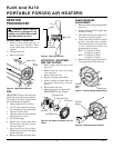
Figure 18 - Removing Burner Head
Burner Head
Spark Plug
Combustion
Chamber
Spark
Plug
Wire
Screw
Air Line
Hose
Fuel Line Hose
Nozzle Seal
Nozzle Face
Nozzle
10. Install blades, pump plate, air filters,
and filter end cover.
11. Replace fan guard and upper shell.
12. Adjust pump pressure (see Pump Pres-
sure Adjustment, page 8).
Note:
If rotor is still binding, proceed
as follows.
13. Perform steps 1 through 6, column 1.
14. Place fine grade sandpaper (600 grit) on
flat surface. Sand rotor lightly in “figure
8” motion four times (see Figure 22).
15. Reinstall insert and rotor.
16. Perform steps 10 through 12.
Burner Head
Fuel Line
Fitting
Air Line Fitting
Figure 19 - Removing Nozzle
9. Blow compressed air through face of
nozzle. This will free any dirt in
nozzle area.
10. Inspect nozzle seal for damage.
11. Replace nozzle into burner head and
tighten firmly (14,300-19,600 grams/
centimeter).
12. Attach burner head to combustion
chamber.
13. Install spark plug in burner head.
14. Attach spark plug wire to spark plug.
15. Connect and route fuel line hose and
air line hose to burner head. See Fuel
and Air Line Replacement and Proper
Routing, page 10.
16. Replace fan (see Fan, page 8).
17. Replace fan guard and upper shell (see
Upper Shell Removal, page 8).