


11
901747
OWNER’S MANUAL
TESTING BURNER FOR
LEAKS
1. Generously apply soapy solution to all
connections.
WARNING: Never check for
gas leaks with open flame.
2. Light the burner with the shut-off valve
no more than half open and holding a
match slightly in front of the pan (see
Lighting Instructions, page 12).
3. Inspect all connections for bubbles, raw
gas odor, or flame from any area other
than the burner (leaks). If leaks are de-
tected, shut off the gas valve immedi-
ately. Tighten, or reassemble the loose
connection(s) using pipe joint com-
pound until burner system is leak free.
4. When the burner is tested and leak free,
observe the individual tongues of flame
on the burner.
Note:
The burner design
includes more ports on the outside of the
bar. Make sure that all ports are clear
and producing flame evenly across the
burner. If any ports appear blocked, clear
them by removing the burner manifold
and reaming the ports with a modified
paper clip or other suitable tool.
5. When finished testing, turn the gas shut-
off valve OFF to extinguish all flames.
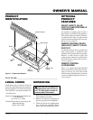
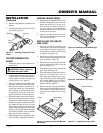
INSTALLATION
Continued
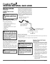
Figure 17 - Installing Propane/LP Pilot
Orifice
Pilot
Injector
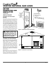
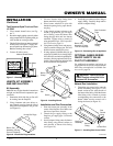
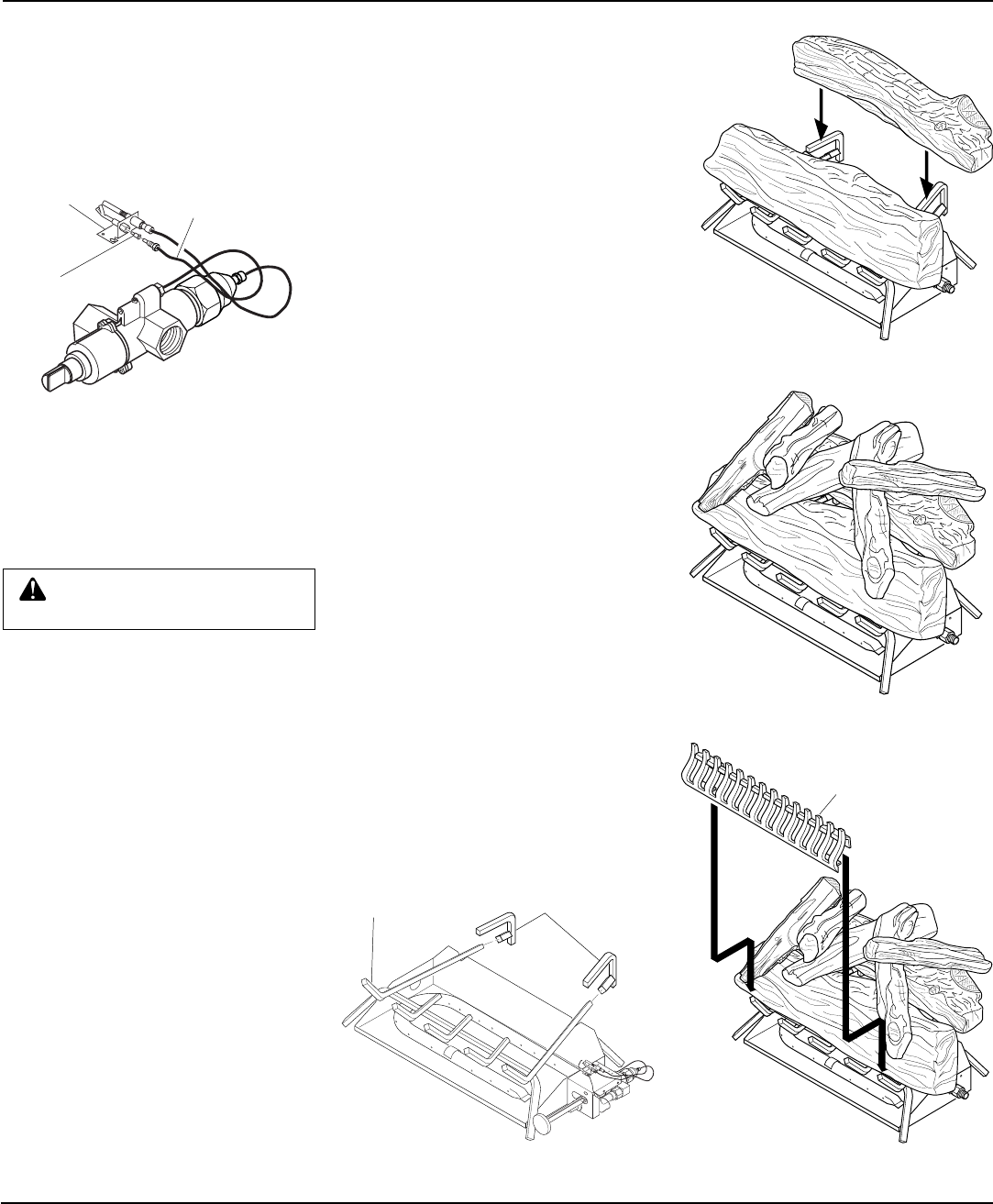
Figure 18 - Installing Grate (Pan Material
Not Shown)
ADDING PAN MATERIAL
1. Open the bag of Ash Bed Material (ver-
miculite) and spread it evenly across the
burner pan to the top. You may over-
flow the front and sides of the pan to
cover the entire pan and connecting
hardware. Do not cover GA9050 series
or GA9150 series valve.
2. Open the glowing embers and evenly
cover the Ash Bed Material (vermicu-
lite) in the burner pan.
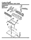
INSTALLING THE GRATE
AND LOGS
1. Place the grate over the burner pan
where the two outer horizontal supports
on the grate fit into the two pan posi-
tioning notches in the rear vertical edge
of the pan (see Figure 18).
2. Slide the two rear log grate steps over
the two outer horizontal supports on the
grate as shown in Figure 18.
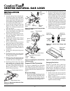
3. Place the front log on the grate and slide
forward against the front bars on the
grate (see Figure 19).
4. Place the back log on the grate onto the
grate steps (see Figure 19).
5. Place the smaller top logs onto the bot-
tom logs (see Figure 20). Leave as
much open space between logs as pos-
sible to minimize flame impingement
and sooting.
Note:
Logs may chip if
they are handled roughly or if hit to-
gether while being placed.
6. Rest the rear tabs of the grate enhancer
on the outside left and right grate bars.
The bottom of the enhancer will rest
against the front of these bars (see Fig-
ure 21).
Figure 19 - Installing Front and Back Logs
Figure 20 - Placement of Top Logs
Grate
Grate Steps
3. Replace and tighten the pilot line to the
bracket.
4. Continue with step 3 under Natural Gas
Installation, page 10.
Figure 21 - Installing Decorative Grill
Grate Enhancer
Pilot Line
Bracket