


www.desatech.com
119421-01A12
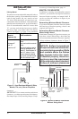
See chart below for minimum permanent ue
opening you must provide. Attach damper clamp
so the minimum permanent ue opening will be
maintained at all times.
INSTALLATION
Continued
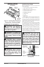
INSTALLING HEATER BASE
ASSEMBLY
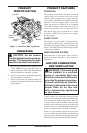
CAUTION: Do not remove the
data plates attached to the heater
base assembly. The data plates
contain important warranty and
safety information.
WARNING: You must secure
this heater to replace oor. If
not, heater will move when you
adjust controls. Moving heater
may cause a gas leak.
WARNING: If installing in a
sunken replace, special care
is needed. You must raise the
replace oor to allow access
to heater control panel. This
will insure adequate air ow
and guard against sooting and
controls being damaged. Raise
replace oor with noncombus-
tible material. Make sure material
is secure.
CAUTION: Do not pick up
heater base assembly by the
burner. This could damage
heater. Only handle base as-
sembly by grates.
IMPORTANT: Make sure the heater burners are
level. If heater is not level, heater will not work
properly.
Installation Items Needed
• hardware package (provided with heater)
• approved exible gas hose (not provided) (if
allowed by local codes)
• sealant resistant to propane (propane/LP) gas,
not provided
• electric drill with 3/16" drill bit
• athead screwdriver
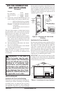
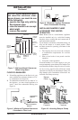
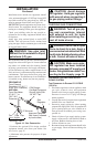
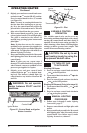
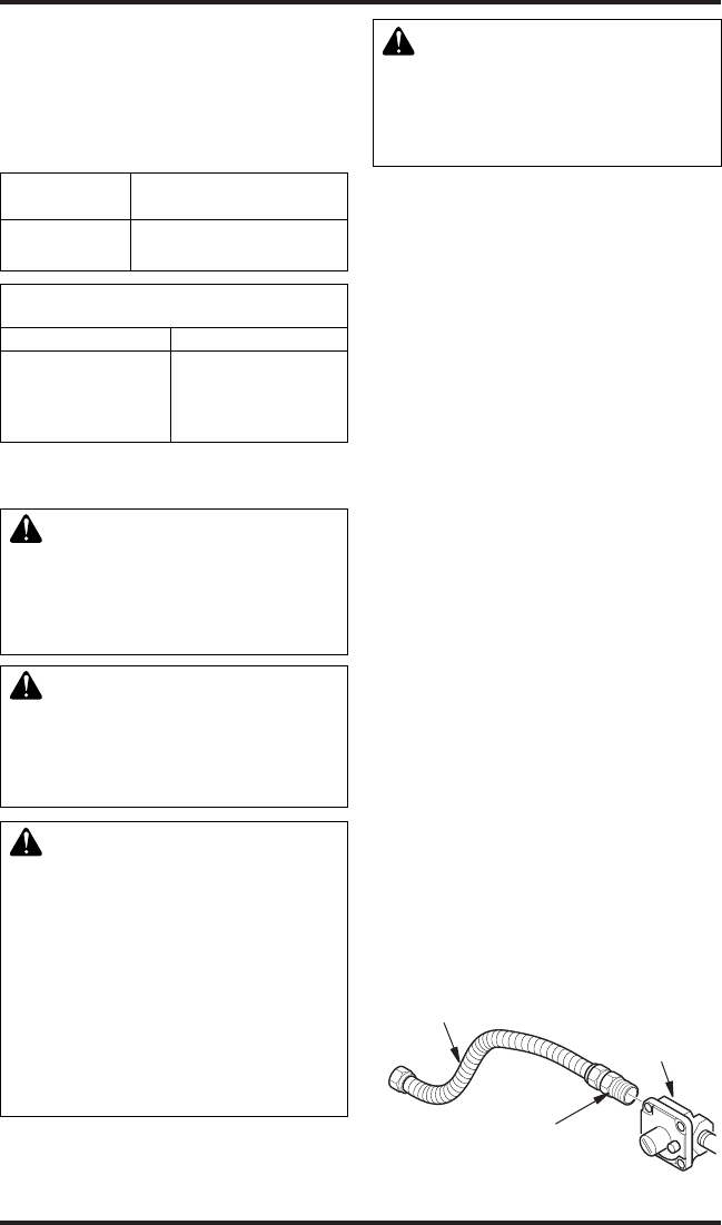
1. Apply pipe joint sealant lightly to male threads
of the tting to be threaded into gas regulator.
Connect approved exible gas hose to gas
regulator of heater (see Figure 11).
IMPORTANT: Hold gas regulator with
wrench when connecting exible gas hose.
2. Locate masonry screws in hardware package.
3. Position heater base assembly in replace.
4. Place logs in their proper position on heater base,
see Installing Logs on page 15.
5. Center heater base and logs front-to-back and
side-to-side in replace.
6. Carefully remove logs without moving
heater base.
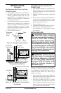
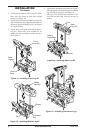
7. Mark screw locations through holes in
mounting brackets (see Figure 12, page 13).
If installing in a brick-bottom replace, mark
screw locations in mortar joint of bricks.
8. Remove heater base from replace.
9. Drill holes at marked locations using 3/16"
drill bit.
10. Attach base assembly to replace oor using
two masonry screws (in hardware package)
(see Figure 12, page 13).
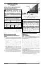
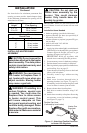
Area of Various Standard
Round Flues
Diameter Area
5" 20 sq. inches
6" 29 sq. inches
7" 39 sq. inches
8" 51 sq. inches
Chimney Minimum permanent
Height Flue Opening
6' to 15' 39 sq. inches
15' to 30' 29 sq. inches
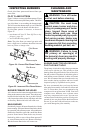
Figure 11 - Attaching Flexible Gas Hose
to Heater Gas Regulator
Heater Gas
Regulator
Flexible Gas Hose
(if allowed by local codes)
Fitting