


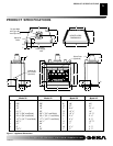
108796-01D
8
For more information, visit www.desatech.com
For more information, visit www.desatech.com
PRE-INSTALLATION
PREPARATION
Continued
PRE-INSTALLATION PREPARATION
Framing
Installing Transition Vent Collar
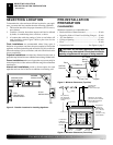
FRAMING
1. Frame appliance enclosure as illustrated in Figures 7 and 8.
Note:
If a wall covering is used to line the enclosure, then all
measurements must be from the surface of the covering.
2. Place the appliance into the framing and secure it.
Note:
If appliance is to be raised above floor level, a platform
must be built to support the appliance.
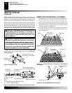
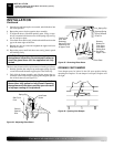
3. Install the supply line to the appliance using a 1/2" NPT black
iron gas line terminating 2
5
/16" above the bottom of the appli-
ance. The gas line may be installed from either side or from the
bottom of the appliance (see Figure 17, page 11).
4. Feed flexible gas line through one of three gas line conduit sleeve
and repack insulation to cover any openings. Prepare the incom-
ing gas line with teflon tape or pipe joint compound and hook-up
incoming gas line to the flexible gas line.
Note:
If 1/2" NPT black iron pipe does not mate with fitting at
the end of flexible gas line, remove fitting and replace with a 37
degree flare 3/4"-12, 1/2" NPT (female) fitting.
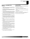
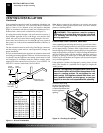
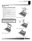
Figure 7 - Rough Opening for Installing in Wall
B
C
A
WARNING: When finishing appliance, do not
overlap combustible material onto the black front
face. Brick, tile, or other noncombustible materials
may be applied to the face provided that any gap is
between the material used and the face is caulked
with a noncombustible caulking.
M36E(B,H) M42E(B,H)
VM36E(B,H) VM42E(B,H)
A 40
3
/8" (1020mm) 44
3
/8" (1121mm)
B 21
3
/8" (543mm) 23
1
/8" (587mm)
C 41
1
/4" (1048mm) 48
1
/4" (1226mm)
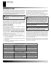
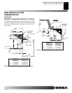
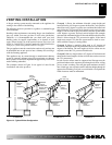
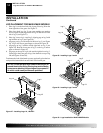
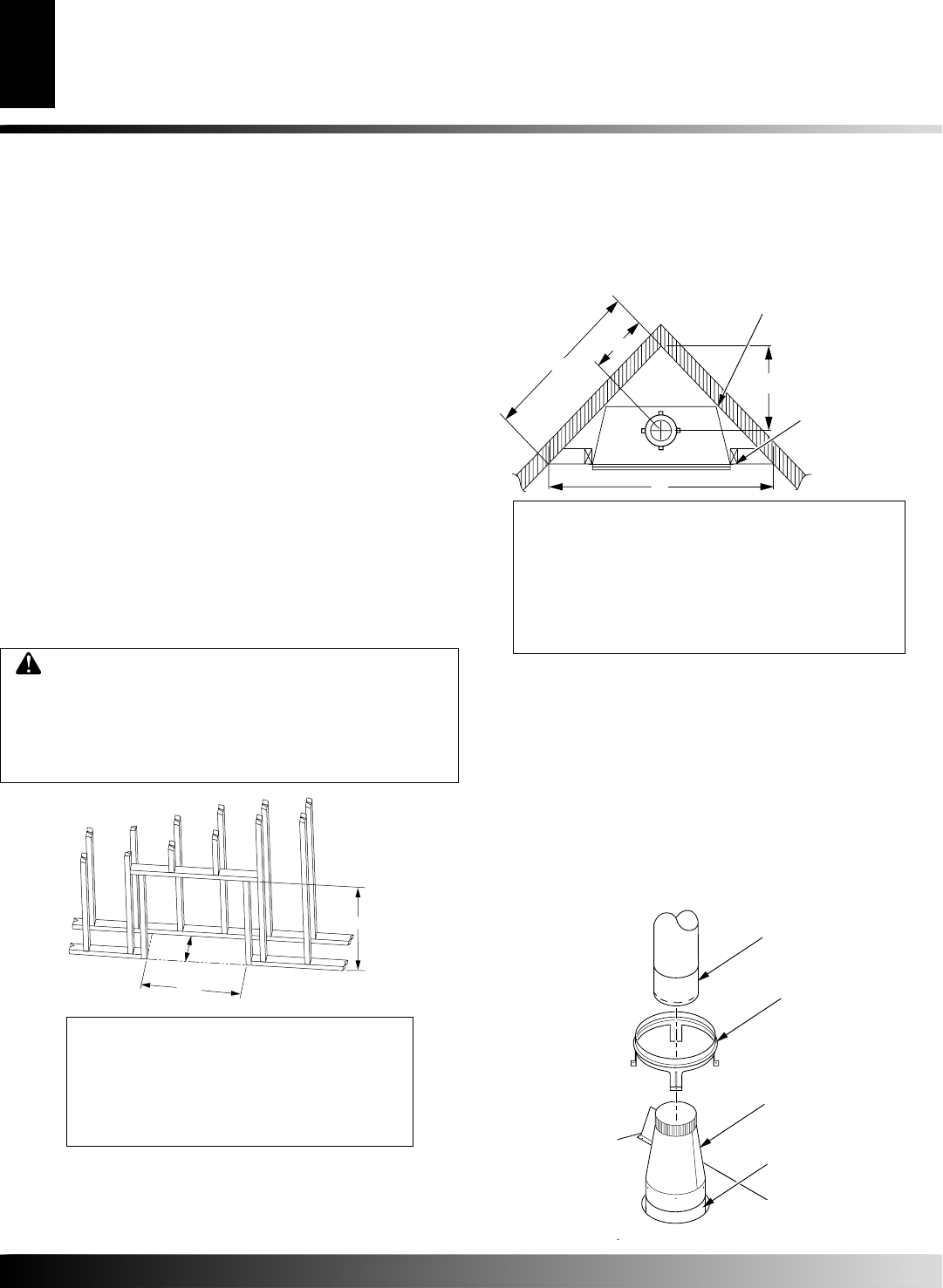
Figure 8 - Corner Installation Guidelines
A
B
C
D
M36E(B,H) M42E(B,H)
VM36E(B,H) VM42E(B,H)
A 24
1
/2"(622.3mm) 27
9
/16"(700.1mm)
B 73
7
/8"(1876.4mm) 83
7
/8"(2130.4mm)
C 52
3
/16"(1326mm) 59
5
/16"(1506.6mm)
D 17
1
/4"(438.2mm) 19
1
/2"(495.3mm)
These Dimensions Allow for a 3/4"
Clearance at Sides and Back of
Fireplace. However, 0" Clearance
is Permitted
3/4" Clearance
Not Required
at Nailing
Flanges
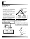
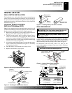
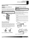
INSTALLING TRANSITION PIPE AND
STARTER COLLAR
The transition pipe and starter collar shown in Figure 9 are supplied
with the fireplace, unattached and ready for installation. Remove the
starter collar and set aside. Slide the transition pipe over the vent
collar and attach with a minimum of three screws. Replace the
starter collar over the transition pipe and attach using four screws
located on the leg stands (five used on the model M42). To install
B-vent piping, slide the first piece of B-vent over the transition pipe
and attach with a minimum of two screws.
Figure 9 - Installing Transition Pipe and Starter Collar
B-Vent Piping
Transition Pipe
Starter Collar
Vent Collar