


www.desatech.com
117001-01A
8
LOCATING HEATER
This heater is designed to be mounted on a wall.
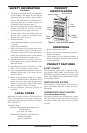
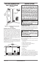
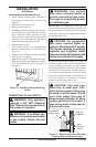
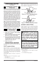
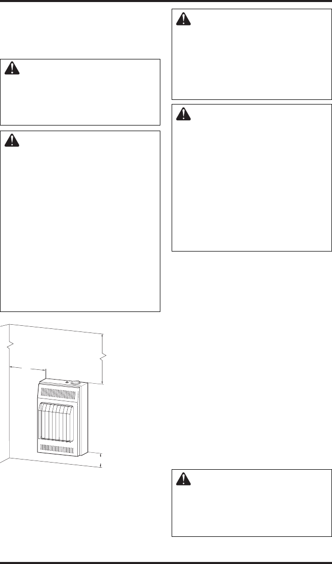
WARNING: Maintain the
minimum clearances shown
in Figure 4. If you can, provide
greater clearances from floor,
ceiling and joining wall.
WARNING: Never install the
heater
• in a bathroom (10,000 Btu/hr
only. 6,000 Btu/hr models are
allowed in a bathroom. Check
local codes.)
• in a recreational vehicle
• where curtains, furniture,
clothing or other flammable
objects are less than 36"
(91.5 cm) from the front, top
or sides of the heater
• as a fireplace insert
• in high traffic areas
• in windy or drafty areas
INSTALLATION
Continued
36" (91.5 cm)
3" (7.7 cm)
FLOOR
CEILING
Minimum
6"
(15.3 cm)
Minimum
From
Sides Of
Heater
Right
Side
Left
Side
Minimum To Top Surface
Of Carpeting, Tile Or Other
Combustible Material
Figure 4 - Mounting Clearances As
Viewed From Front of Heater
CAUTION: If you install the
heater in a home garage
• heater pilot and burner must
be at least 18" (45.7 cm) above
floor
• locate heater where moving
vehicle will not hit it
CAUTION: This heater cre-
ates warm air currents. These
currents move heat to wall sur-
faces next to heater. Installing
heater next to vinyl or cloth wall
coverings or operating heater
where impurities (such as, but
not limited to, tobacco smoke,
aromatic candles, cleaning flu-
ids, oil or kerosene lamps, etc.) in
the air exist, may discolor walls
or cause odors.
IMPORTANT: Vent-free heaters add moisture to
the air. Although this is beneficial, installing heater
in rooms without enough ventilation air may cause
mildew to form from too much moisture. See Air
for Combustion and Ventilation, page 5. If high hu-
midity is experienced, a dehumidifier may be used
to help lower the water vapor content in the air.
For convenience and efficiency, install heater
• where there is easy access for operation, inspec
-
tion and service
• in coldest part of room
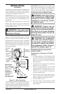
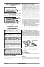
THERMOSTAT SENSING BULB
(Thermostat Models Only)
The thermostat sensing bulb is located inside the
heater. Do not move this bulb during installation
or operation of the heater.
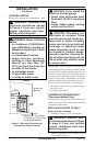
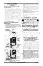
INSTALLING HEATER TO WALL
Marking Screw Locations
1. Determine where you will locate heater.
WARNING: Maintain mini-
mum clearances shown in Figure
5, page 9. If you can, provide
greater clearances from floor
and joining wall.
2. Mark two mounting screw locations on wall
(see Figure 5, page 9).