


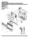
14
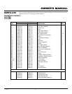
105568
BLUE FLAME NATURAL GAS HEATER
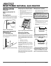
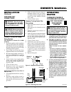
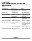
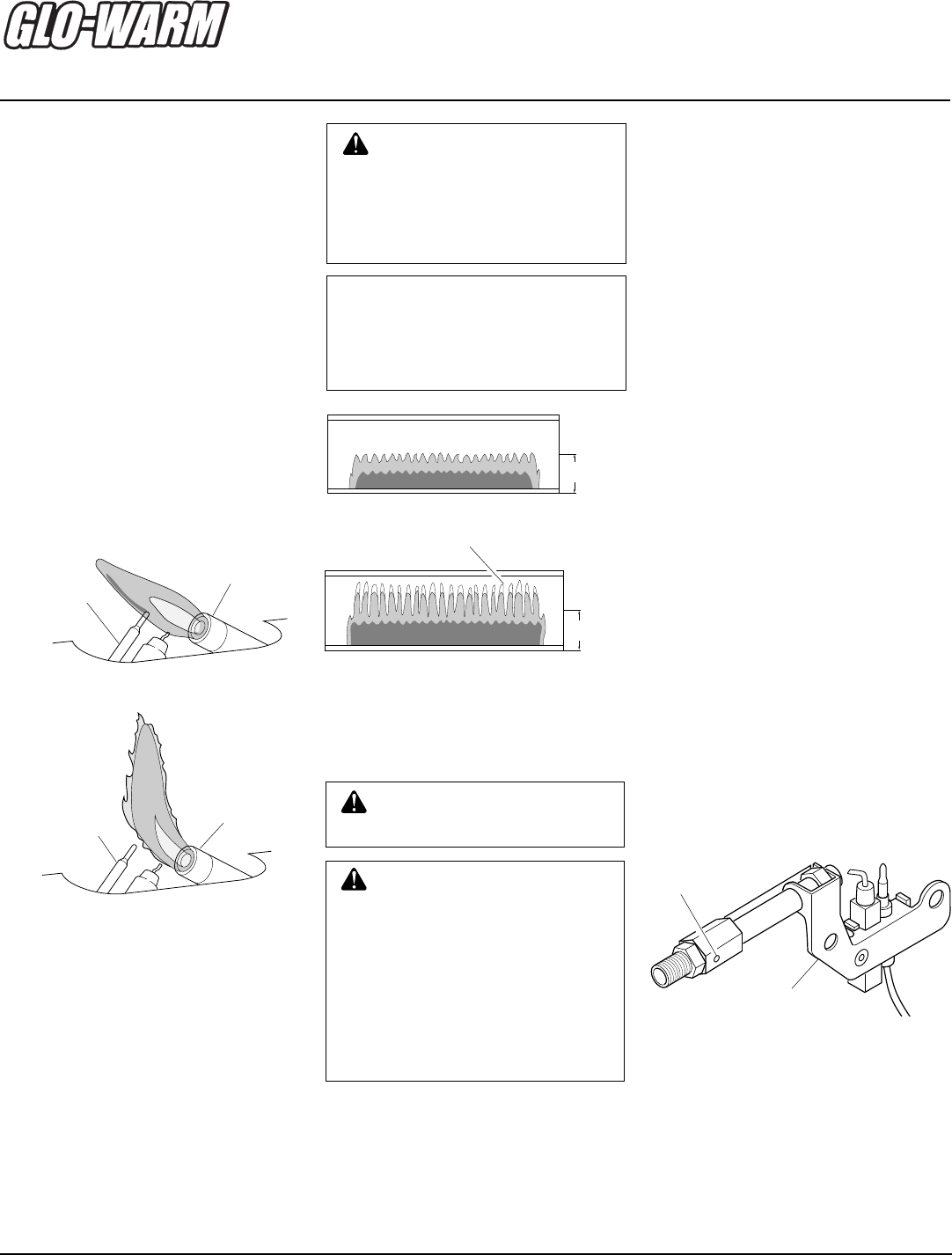
Figure 21 - Incorrect Pilot Flame Pattern
Thermocouple
Pilot Burner
INSPECTING
BURNER
Check pilot flame pattern and burner flame
pattern often.
PILOT FLAME PATTERN
Figure 20 shows a correct pilot flame pattern.
Figure 21 shows an incorrect pilot flame
pattern. The incorrect pilot flame is not touch-
ing the thermocouple. This will cause the
thermocouple to cool. When the thermo-
couple cools, the heater will shut down.
If pilot flame pattern is incorrect, as shown
in Figure 21
• turn heater off (see To Turn Off Gas to Ap-
pliance, page 12 for thermostat models or
page 13 for non-thermostat models)
• see Troubleshooting, pages 15 through 17
Figure 20 - Correct Pilot Flame Pattern
Thermocouple
Pilot Burner
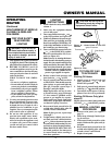
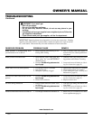
BURNER FLAME PATTERN
Figure 22 shows a correct burner flame
pattern. Figure 23 shows an incorrect burner
flame pattern. The incorrect burner flame
pattern shows yellow tipping of the flame. It
also shows the flame higher than 1/2 the
glass panel height.
If burner flame pattern is incorrect, as shown
in Figure 23
• turn heater off (see To Turn Off Gas To Ap-
pliance, page 12 for thermostat models or
page 13 for non-thermostat models)
• see Troubleshooting, pages 15 through 17
1/2
G
Figure 22 - Correct Burner Flame Pattern
Yellow Tipping
1/2
G
Figure 23 - Incorrect Burner Flame Pattern
NOTICE: Do not mistake orange
flames with yellow tipping. Dirt
or other fine particles enter the
heater and burn causing brief
patches of orange flame.
WARNING: If yellow tipping
occurs, your heater could pro-
duce increased levels of carbon
monoxide. If burner flame pattern
shows yellow tipping, follow in-
structions at bottom of this page.
CLEANING AND
MAINTENANCE
WARNING: Turn off heater
and let cool before cleaning.
CAUTION: You must keep
control areas, burner, and circu-
lating air passageways of heater
clean. Inspect these areas of
heater before each use. Have
heater inspected yearly by a quali-
fied service person. Heater may
need more frequent cleaning due
to excessive lint from carpeting,
bedding material, pet hair, etc.
1
/2 Glass
Height
1
/2 Glass
Height
ODS/PILOT AND BURNER
• Use a vacuum cleaner, pressurized air,
or small, soft bristled brush to clean.
CLEANING BURNER
PILOT AIR INLET HOLE
We recommend that you clean the unit every
2,500 hours of operation or every three months.
We also recommend that you keep the burner
tube and pilot assembly clean and free of dust
and dirt. To clean these parts we recommend
using compressed air no greater than 30 PSI.
Your local computer store, hardware store, or
home center may carry compressed air in a
can. You can use a vacuum cleaner in the
blow position. If using compressed air in a
can, please follow the directions on the can.
If you don't follow directions on the can, you
could damage the pilot assembly.
1. Shut off the unit, including the pilot.
Allow the unit to cool for at least thirty
minutes.
2. Inspect burner, pilot for dust and dirt.
3. Blow air through the ports/slots and
holes in the burner.
Clean the pilot assembly also. A yellow tip
on the pilot flame indicates dust and dirt in
the pilot assembly. There is a small pilot air
inlet hole about two inches from where the
pilot flame comes out of the pilot assembly
(see Figure 24). With the unit off, lightly
blow air through the air inlet hole. You may
blow through a drinking straw if compressed
air is not available.
Figure 24 - Pilot Inlet Air Hole
Pilot Assembly
Pilot Air Inlet
Hole
CABINET
Air Passageways
• Use a vacuum cleaner or pressurized air
to clean.
Exterior
• Use a soft cloth dampened with a mild
soap and water mixture. Wipe the cabi-
net to remove dust.