


8
107297
INFRARED PROPANE/LP GAS HEATER
17
3
/
8
"
17
1
/
2
"
Min.
6
1
/
2
"
Min.
Adjoining Wall
Only Insert Mounting
Screws Through Last
Hole On Each End
Floor
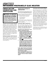
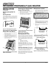
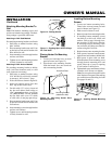
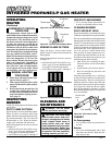
Methods For Attaching
Mounting Bracket To Wall
Only use last hole on each end of mounting
bracket to attach bracket to wall. These two
holes are 16 inches apart from their centers.
Attach mounting bracket to wall in one of
two ways
1. Attaching to wall stud
2. Attaching to wall anchor
Attaching to Wall Stud: This method pro-
vides the strongest hold. Insert mounting
screws through mounting bracket and into
wall studs.
Attaching to Wall Anchor: This method
allows you to attach mounting bracket to
hollow walls (wall areas between studs) or
to solid walls (concrete or masonry).
Decide which method better suits your needs.
Either method will provide a secure hold for
the mounting bracket.
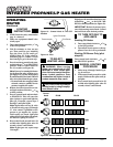
Marking Screw Locations
1. Tape mounting bracket to wall where
heater will be located. Make sure
mounting bracket is level.
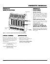
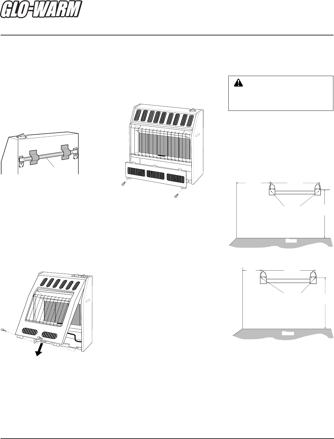
Models FB-5B, FBS-5B
Models FB-3B, FBS-3B
Figure 9 - Mounting Bracket Clearances
WARNING: Maintain minimum
clearances shown in Figure 8. If
you can, provide greater clear-
ances from floor and joining wall.
INSTALLING HEATER TO
WALL
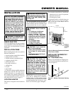
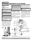
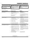
Mounting Bracket
The mounting bracket is located on back
panel of heater. It has been taped there for
shipping. Remove mounting bracket from
back panel.
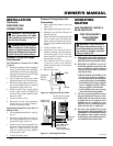
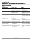
Removing Front Panel Of Heater
Models FBS-3C and FBS-5C
1. Remove two screws near bottom cor-
ners of front panel.
2. Lift straight up on grill guard until it stops.
Grill guard will slide up about 1/4".
3. Pull bottom of front panel forward, then
down (see Figure 7).
Figure 6 - Mounting Bracket Location
Mounting
Bracket
INSTALLATION
Continued
Figure 7 - Removing Front Panel of Heater
(Model FBS-3B Shown)
Removing Front Panel Of Heater
Models FB-3B and FB-5B
1. Remove two screws near bottom cor-
ners of lower front panel.
2. Pull bottom of lower front panel for-
ward, then down (see Figure 8).
Figure 8 - Removing Front Panel of Heater
(Model FB-5B Shown)
2. Mark screw locations on wall (see Fig-
ure 9).
Note:
Only mark last hole on each end
of mounting bracket. Insert mounting
screws through these holes only.
3. Remove tape and mounting bracket
from wall.
17
1
/
2
"
Min.
10
1
/
4
"
Min.
17
3
/
8
"
Adjoining Wall
Only Insert Mounting
Screws Through Last
Hole On Each End
Floor