


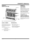
11
105566
OWNER’S MANUAL
CHECKING GAS
CONNECTIONS
Pressure Testing Gas Supply
Piping System
Test Pressures In Excess Of 1/2 PSIG
(3.5 K Pa)
1. Disconnect heater and its individual
manual shutoff valve from gas supply
piping system. Pressures in excess of
1/2 PSIG will damage heater regulator.
2. Cap off open end of gas pipe where
manual shutoff valve was connected.
3. Pressurize supply piping system by ei-
ther using compressed air or opening
main gas valve located on or near gas
meter.
4. Check all joints of gas supply piping
system. Apply mixture of liquid soap
and water to gas joints. Bubbles form-
ing show a leak.
5. Correct all leaks at once.
6. Reconnect heater and manual shutoff
valve to gas supply. Check reconnected
fittings for leaks.
Test Pressures Equal To or Less Than
1/2 PSIG (3.5 K Pa)
1. Close manual shutoff valve (see Fig-
ure 14).
2. Pressurize supply piping system by ei-
ther using compressed air or opening
main gas valve located on or near gas
meter.
WARNING: Never use an open
flame to check for a leak. Apply a
mixture of liquid soap and water
to all joints. Bubbles forming
show a leak. Correct all leaks at
once.
WARNING: Test all gas pip-
ing and connections for leaks
after installing or servicing. Cor-
rect all leaks at once.
3. Check all joints from gas meter to manual
shutoff valve (see Figure 15). Apply mix-
ture of liquid soap and water to gas joints.
Bubbles forming show a leak.
4. Correct all leaks at once.
Pressure Testing Heater Gas
Connections
1. Open manual shutoff valve (see Figure 14).
2. Open main gas valve located on or near
gas meter.
3. Make sure control knob of heater is in
the OFF position.
4. Check all joints from manual shutoff
valve to control valve (see Figure 15).
Apply mixture of liquid soap and wa-
ter to gas joints. Bubbles forming show
a leak.
5. Correct all leaks at once.
6. Light heater (see Operating Heater,
page 12 for non-thermostat models or
page 13 for thermostat models). Check
the rest of the internal joints for leaks.
7. Turn off heater (see To Turn Off Gas
to Appliance, page 13 for non-thermo-
stat models or page 14 for thermostat
models).
8. Replace front panel.
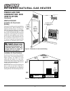
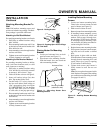
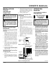
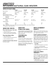
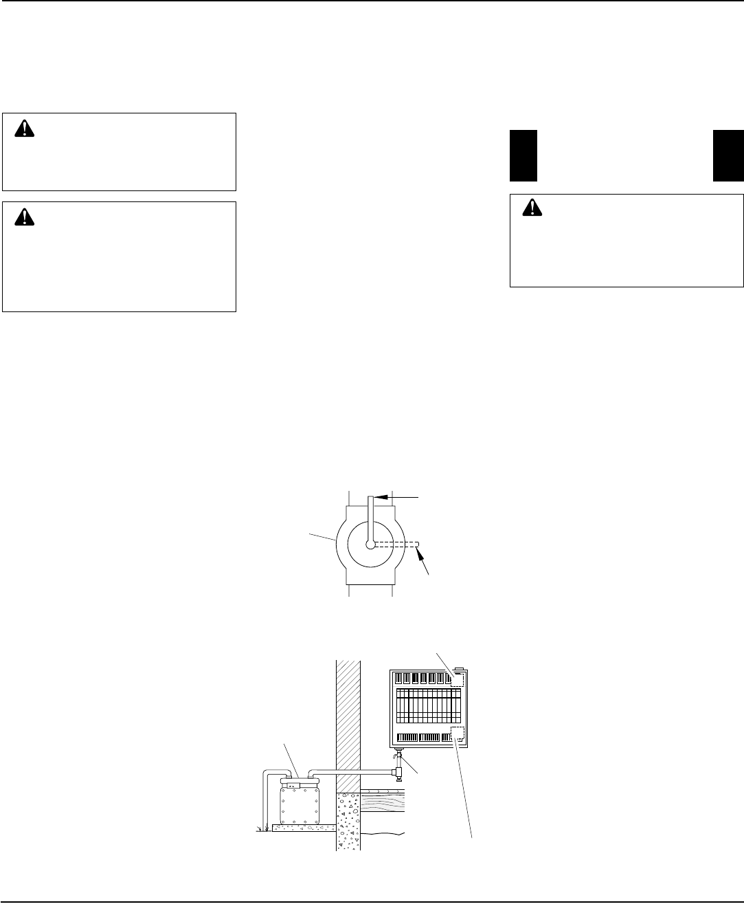
Figure 14 - Manual Shutoff Valve
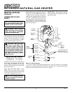
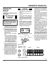
Figure 15 - Checking Gas Joints
Gas Meter
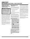
OPERATING
HEATER
NON-THERMOSTAT MODELS
FA-3B AND FA-5B
INSTALLATION
Continued
Continued
FOR YOUR SAFETY
READ BEFORE
LIGHTING
A. This appliance has a pilot which must
be lighted by hand. When lighting the
pilot, follow these instructions exactly.
B. BEFORE LIGHTING smell all
around the appliance area for gas. Be
sure to smell next to the floor because
some gas is heavier than air and will
settle on the floor.
WHAT TO DO IF YOU SMELL
GAS
• Do not try to light any appliance.
• Do not touch any electric switch; do
not use any phone in your building.
• Immediately call your gas supplier
from a neighbor’s phone. Follow
the gas supplier’s instructions.
• If you cannot reach your gas sup-
plier, call the fire department.
C. Use only your hand to push in or turn
the gas control knob. Never use tools.
If the knob will not push in or turn
by hand, don’t try to repair it, call a
qualified service technician or gas
supplier. Force or attempted repair
may result in a fire or explosion.
D. Do not use this appliance if any part
has been under water. Immediately
call a qualified service technician to
inspect the appliance and to replace
any part of the control system and
any gas control which has been un-
der water.
WARNING: If you do not fol-
low these instructions exactly, a
fire or explosion may result caus-
ing property damage, personal
injury or loss of life.
Manual
Shutoff
Valve
Control Valve Location
Non-Thermostat Models
Control Valve Location
Thermostat Models
O
PO
S
P
Manual
Shutoff
Valve
Closed
Open