


9
105564
OWNER’S MANUAL
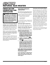
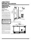
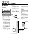
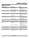
Tee Joint
Reducer
Bushing to
1/8" NPT
1/8" NPT
Plug Tap
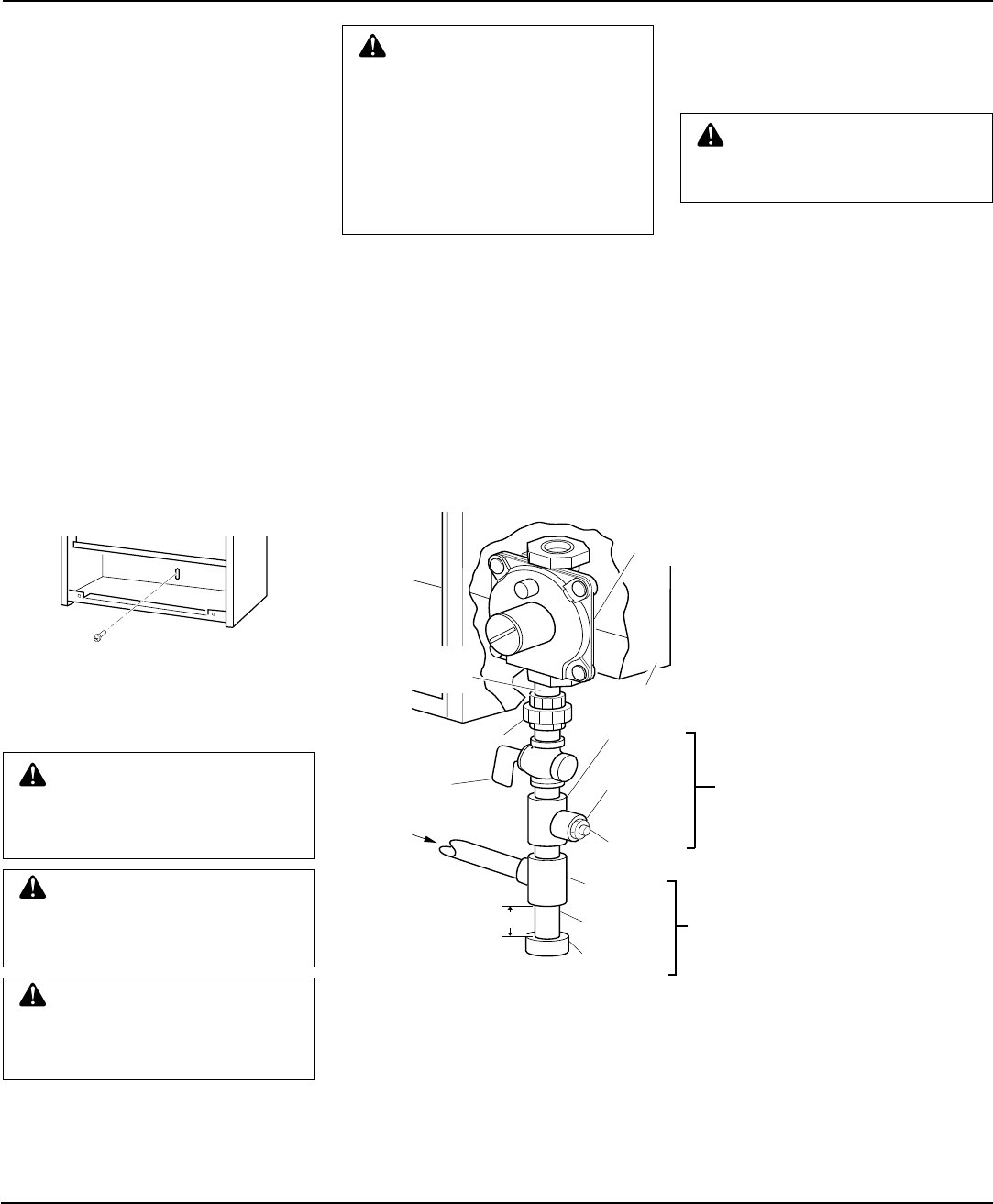
Figure 13 - Gas Connection
* An CSA/AGA design-certified equipment shutoff valve with 1/8" NPT tap is an
acceptable alternative to test gauge connection. Purchase the optional CSA/AGA design-
certified equipment shutoff valve from your dealer. See Accessory, page 18.
INSTALLATION
Continued
Continued
CONNECTING TO GAS
SUPPLY
WARNING: A qualified ser-
vice person must connect heater
to gas supply. Follow all local
codes.
IMPORTANT:
Check gas line pressure be-
fore connecting heater to gas line. Gas line
pressure must be no greater than 14 inches
of water. If gas line pressure is higher,
heater regulator damage could occur.
Install sediment trap in supply line as shown
in Figure 13. Locate sediment trap where it
is within reach for cleaning. Locate sedi-
ment trap where trapped matter is not likely
to freeze. A sediment trap traps moisture
and contaminants. This keeps them from
going into heater controls. If sediment trap
is not installed or is installed wrong, heater
may not run properly.
IMPORTANT:
Hold pressure regulator with
wrench when connecting it to gas piping
and/or fittings
Installation must include an equipment
shutoff valve, union, and plugged 1/8" NPT
tap. Locate NPT tap within reach for test
gauge hook up. NPT tap must be upstream
from heater (see Figure 13).
IMPORTANT:
Install an equipment shutoff
valve in an accessible location. The equip-
ment shutoff valve is for turning on or
shutting off the gas to the appliance.
CAUTION: Never connect heater
to private (non-utility) gas wells.
This gas is commonly known as
well-head gas.
CAUTION: Use only new,
black iron or steel pipe. Inter-
nally-tinned copper tubing may
be used in certain areas. Check
your local codes. Use pipe 3/8"
diameter or greater to allow
proper gas volume to heater. If
pipe is too small, undue loss of
pressure will occur.
CAUTION: Use pipe joint seal-
ant that is resistant to liquid pe-
troleum (LP) gas.
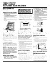
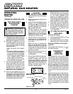
Figure 12 - Installing Bottom Mounting
Screw
Test
Gauge
Connection *
Tee Joint
Pipe Nipple
Cap
Pressure
Regulator
Heater
Cabinet
3/8" NPT
Pipe Nipple
Ground Joint Union
Sediment
Trap
Equipment
Shutoff
Valve *
From
Gas Meter
(4" W.C. to
10.5" W.C.
Pressure)
3" Min.
4. If installing bottom mounting screw into
hollow or solid wall, install wall anchor.
Follow steps 1 through 4 under Attach-
ing To Wall Anchor Method, page 8. If
installing bottom mounting screw into
wall stud, drill holes at marked loca-
tions using 9/64" drill bit.
5. Replace heater onto mounting bracket.
6. Place spacer between bottom mount-
ing hole and wall anchor or drilled hole.
7. Hold spacer in place with one hand.
With other hand, insert mounting screw
through bottom mounting hole and
spacer. Place tip of screw in opening
of wall anchor or drilled hole.
8. Tighten screw until heater is firmly secured
to wall. Do not over tighten.
Note:
Do not
replace front panel at this time. Replace
front panel after making gas connections
and checking for leaks. (see page 10).
Apply pipe joint sealant lightly to male
threads. This will prevent excess sealant
from going into pipe. Excess sealant in pipe
could result in clogged heater valves.
WARNING: This appliance re-
quires a 3/8" NPT (National Pipe
Thread) inlet connection to the
pressure regulator.